Adjustments, Miter scale (vernier) indicator adjustment, Crown molding detent adjustment (bevel) – Bosch 3912 User Manual
Page 42: Crown molding detent adjustment, Caution
42
Adjustments
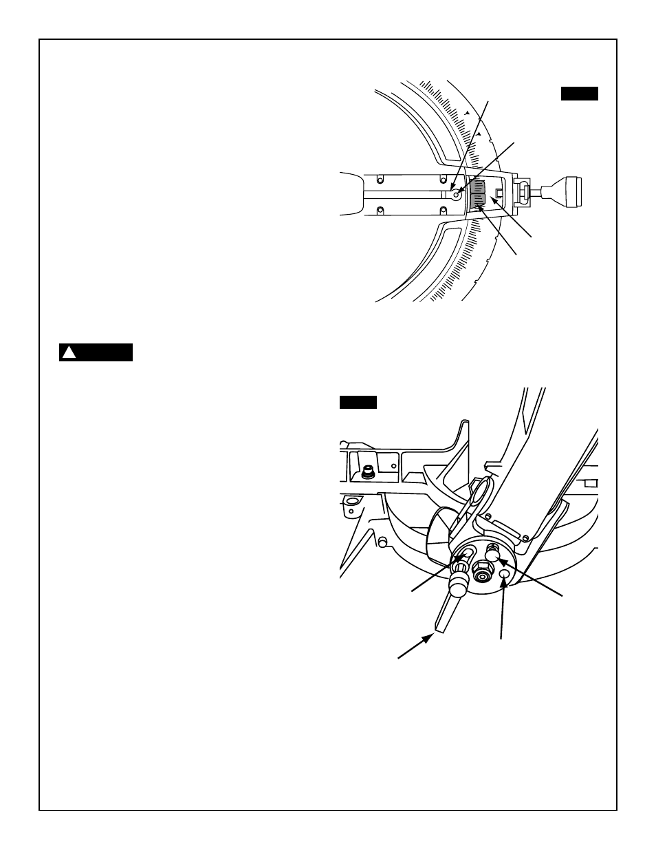
Miter Scale (Vernier) Indicator
Adjustment
1.
Raise the head assembly to the full-up position.
2.
Through the slot 1 in the kerf insert, loosen the Phillips
screw 2 that holds the indicator 3 in place (Figure 14).
3.
Position the indicator 3 to align with the 0° miter mark 4.
Tighten the screw 2.
Crown Molding Detent
Adjustment (Bevel)
1.
Move sliding fence to proper position. (See Sliding
Fence on page 54.)
2.
Pull crown molding detent pin out and rotate pin 90° so
it stays in the out position.
Keep pin in out position for all operations
except when cutting crown molding.
3.
Loosen bevel lock handle 5. Rotate head assembly to
33.9° on the bevel scale. Insert the pin 6 into the detent,
tighten the bevel lock handle 5 (Figure 15).
4.
Measure the angle between the blade and the table. If it
is not 33.9° follow the procedures for the crown molding
detent adjustment.
Crown Molding Detent Adjustment
a.
Remove plastic plug 7.
b.
Loosen crown molding detent adjusting hex head
cap screw 8 using the 6mm Hex "L" Wrench.
c.
Loosen bevel lock handle 5.
d.
Move the head assembly, with the pin 6 still
inserted into the detent, to 33.9°.
e.
Tighten bevel lock handle 5. Tighten adjusting
screws 7.
40
35
30
25
20
15
10
5
0
5
10
15
20
25
316
225
30
35
40
45
FIG. 14
FIG. 15
2
4
3
1
6
5
7
8
CAUTION
!