Service, Page 21 – Bunn Dual Voltage Models Starting at Serial #024477 CDBC User Manual
Page 21
Page 21
CA
UTION :
WARMERS AND SURFACES ARE HOT
CAUTION
DIS
CA
RD D
EC
AN
TE
R
IF:
!
BUNN
MANUFACTURED BY BUNN-O-MATIC CORPORATION
SPRINGFIELD, ILLINOIS, U.S.A.
MODEL
S/N
VOLTS A.C. AMP WATTS
PHASE WIRE HERTZ
COVERED UNDER ONE OR MOREOF THE FOLLOWING PATENTS :
ONE OR MORE OTHER PATENTS MAY BE PENDING
!
CAUTION
DIS
CA
RD
D
EC
AN
TER
IF:
. C
RA
CK
ED
. S
CR
AT
CH
ED
. BO
ILE
D D
RY
. HE
AT
ED
W
HE
N
EM
PT
Y
. U
SE
D O
N H
IG
H F
LA
ME
. O
R E
XP
OS
ED
E
LE
CT
RIC
E
LE
ME
NT
S
FA
ILU
RE
TO
CO
MP
LY
R
IS
KS
IN
JU
RY
PN
: 6
58
19
85
BU
NN
-O
-M
ATIC
C
OR
PO
RA
TIO
N
FU
NN
EL C
ON
TE
NTS
A
RE
H
OT
!
SERVICE
This section provides procedures for testing and
replacing various major components used in this
brewer should service become necessary. Refer to
Troubleshooting for assistance in determining the
cause of any problem.
WARNING - Inspection, testing, and repair of electri-
cal equipment should be performed only by qualified
service personnel. The brewer should be unplugged
when servicing, except when electrical tests are re-
quired and the test procedure specifically states to
plug in the brewer.
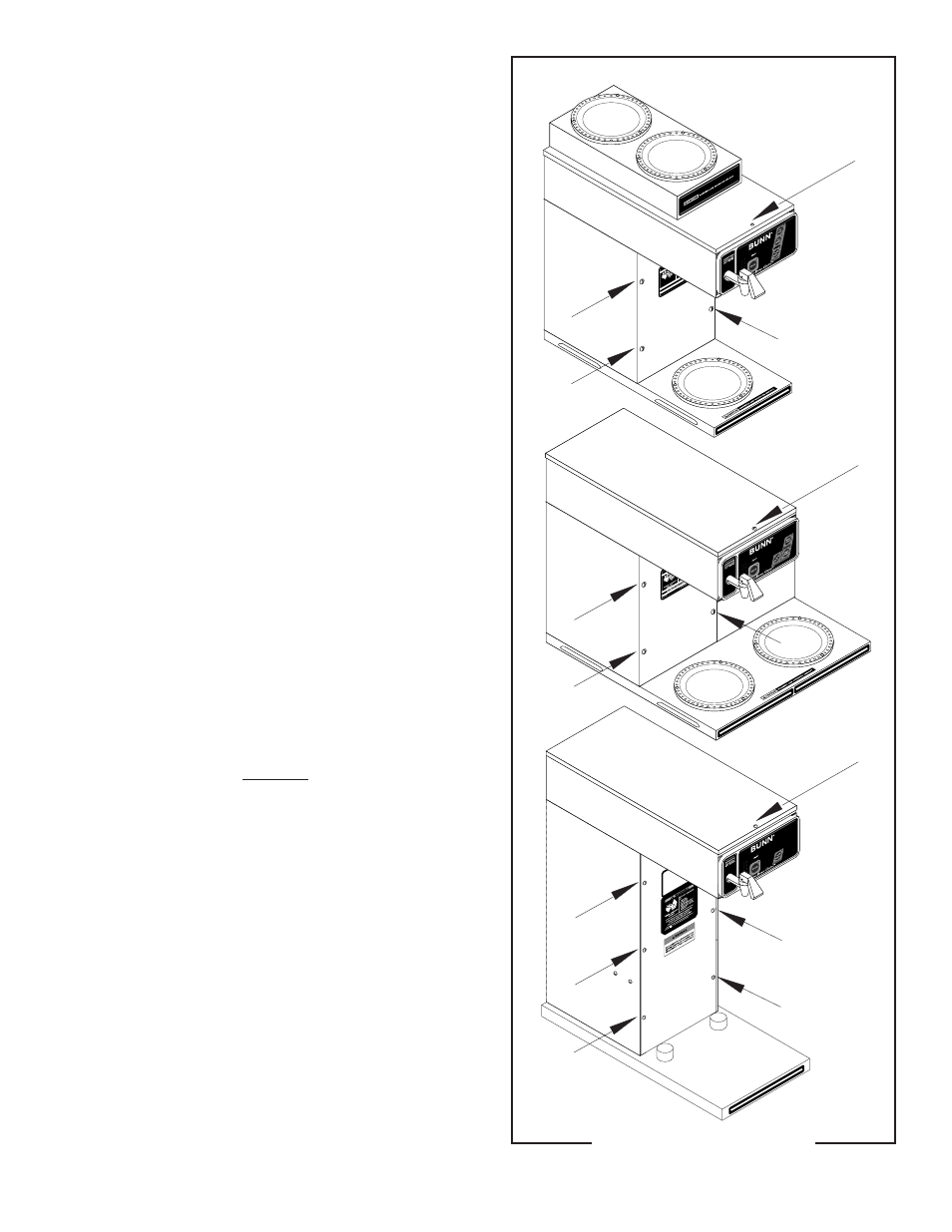
COMPONENT ACCESS
WARNING - Disconnect the brewer from the power
source before the removal of any panel or the replace-
ment of any component.
All components are accessible by the removal of
the top cover or warmer housing, front access panel
and warmer plate(s).
The top cover is attached with one #4-40 screw.
The front access panel is attached with four #6-32
screws.
Each warmer assembly is attached with three #4-
40 screws.
P1889
Contents
Control Board .................................................... 22
Switch Panel ...................................................... 23
Dispense Valve .................................................. 24
Limit Thermostat ............................................... 25
Tank Heaters ...................................................... 26
Voltage Selector Switch ..................................... 28
Refill Valve ......................................................... 29
Warmer Elements .............................................. 30
Wiring Diagrams ............................................... 31
FIG. 1 COMPONENT ACCESS
29707.1 082803