4attach motors, 7attach propellers, 5reassemble stack-ups and apm – 3D Robotics 3DR Hexa-to-Y6 Conversion Kit User Manual
Page 2: 6test motor spin directions, 3attach legs, Attach mounting plates to bottom motors, Attach legs to arms, Insert mounting plate between top motor and arm, Attach top and bottom mounting plates, Reconnect motors to escs and pdb
Threadlocking compound is an important component to ensure your motors
remain firmly attached! For more information, check out this helpful video:
http://goo.gl/bM3MA
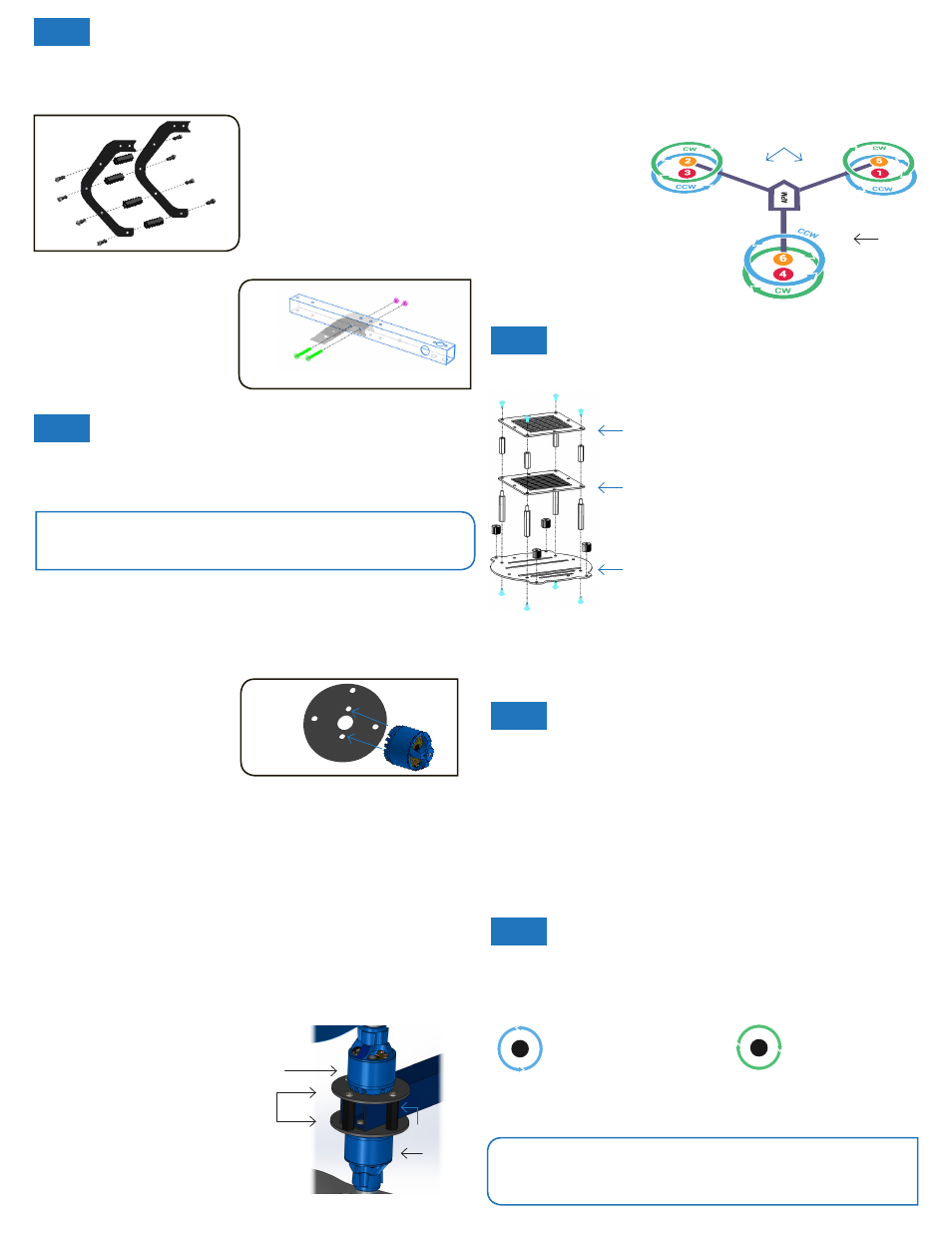
Attach mounting plates to bottom motors
Each arm of your Y6 will have a top motor and a bottom motor attached to the
arm using a motor mounting plate. To ensure motors are securely bolted to
arms, apply a small amount of threadlock to each bolt before fastening.
First we’ll attach the mounting plates to the bottom motors using two 5 mm
bolts (you should have these from when we disconnected the motors from the
arms) and one motor mounting plate (from conversion kit).
Attach legs to arms with C-shape
facing outwards using two 25 mm
steel bolts and two metal nuts.
(You should have bolts and nuts
from when we detached the legs
from the Hexa.)
For each hole, position spacer between
holes; secure from each side with bolts.
Repeat for all four holes. Repeat for all
three legs.
Leg assembly I
Attach legs to arms
4
Attach motors
Insert mounting plate between top motor and arm
Now we’ll attach the top motors to the arms. Insert mounting plate between
top motor and arm. Make sure motor cables protrude in the direction of the
end of the arm.
Fasten motor and plate to arm using two 5 mm bolts by accessing through
the two large holes in the bottom of the arm.
Repeat for all three arms.
Place mounting plate (with bottom motor attached) on underside of arm so
that three outer holes align. Insert 19 mm hollow spacer between top and
bottom hole; thread 25 mm steel bolt through spacer and plates. Secure
with nut. Repeat for all three holes on mounting plates.
Repeat for all three arms.
Top and bottom motors attached
to arm with mounting plates
Attach
motor
here
Bottom motor
assembly
Position motor onto plate as shown.
Fasten plate to motor using two
bolts. Repeat for three motors.
Attach top and bottom mounting plates
Top motor
Mounting
plates
Bottom
motor
Spacer
Note: Bottom motor
does not connect
directly to arm.
Reconnect motors to ESCs and PDB
Thread top and bottom motor cables through opening in end of arm.
Connect motor cable bullet connectors to ESC bullet connectors.
7
Attach propellers
Connect ESC Deans connectors to PDB Deans connectors. (Order doesn’t
matter; this is just to provide power to the motors.) Repeat for all three arms.
Black
arm
Blue arms
Connect ESC three-wire
cables to signal pins on
PDB according to motor
number. Motor numbers
are configured as shown.
Attach 10-inch propellers to top motors and 11-inch propellers to bottom
motors according to the configuration shown above. Pusher propellers are
marked “4.7P”; normal propellers are marked “4.7”. If using metal spacers,
place metal spacer on top of propeller before adding prop nut.
Regardless of motor orientation, all propellers must face up (markings on
top). This means that you’ll need to attach propellers to bottom motors
upside down.
5
Reassemble stack-ups and APM
Attach mounting plate to frame with
thumbnuts. Attach stack-ups to mounting
plate using original spacers and bolts as
shown.
Make sure your APM is facing forward,
between the two blue arms as shown in
the diagram above.
If necessary rotate the APM and/or stack-
up plate to achieve this.
PDB signal pins are labelled M1 through
M6. Connect motors to their respective
signal pins with white wire positioned
upward.
Reconnect GPS cable, power module cable, cables from PDB into output pins,
cables from receiver into input pins, 3DR Radio into telemetry port, and any
other cables that were disconnected from your APM during step 1.
6
Test motor spin directions
Connect battery to your Y6. Test motors to ensure that propellers will spin in
the correct directions as specified in the diagram above. CW (green) signifies
clockwise rotation; CCW (blue) signifies counterclockwise rotation.
If motor spins in the incorrect direction, switch two of the three cables
joining the motor and ESC. Once correct spin directions are confirmed,
secure ESCs to arms using zip ties.
Note: If your motor and ESC cables were originally soldered, resolder cables
here once motors are confirmed to spin in correct directions.
Your Y6 conversion is complete! For pre-flight configuration, Y6
firmware download, and additional setup instructions, please visit:
www.copter.ardupilot.com/apmcopter
. Happy flying!
Top stack-up
Bottom
stack-up
Mounting
plate
Now that your copter is configured into a Y6, we’ll reattach the stack-ups and
reconnect the hardware.
©2013 3D Robotics
Your Y6 has three legs, each comprised of two C-type landing gear pieces. To
assemble each leg, align the two pieces and attach through four bottom holes
using four 18 mm threaded hex spacers and eight 5 mm nylon bolts.
3
Attach legs
Leg assembly II
CCW
!
!
CW
CCW
!
!
CW
COUNTERCLOCKWISE ROTATION:
USE NORMAL PROPELLER
CLOCKWISE ROTATION:
USE PUSHER PROPELLER