Hutoffs, Pply the, Ads to a – Wood’s Powr-Grip MT10HV11FDCO User Manual
Page 11
Rev 19.0/1-13
9
MT-HV11FDCO: #35093
T
O
U
SE
P
AD
S
HUTOFFS
Each shutoff on the pad frame controls the vacuum line to the adjacent vacuum pad. By
activating or deactivating the vacuum flow at specific pads, the operator can use the lifter to
handle loads of various weights and dimensions (see Load Capacity and Pad Spread in
SPECIFICATIONS). In addition, certain pads may be deactivated in order to avoid holes in the
load surface. To support the maximum load weight and larger load dimensions, all pads must be
activated; for smaller weights and dimensions, some pads may be deactivated,
provided that
the lifter still has sufficient capacity to support the load
(see INTENDED USE: L
OAD
C
HARACTERISTICS
).
WARNING: Closing any pad shutoff reduces lifting capacity.
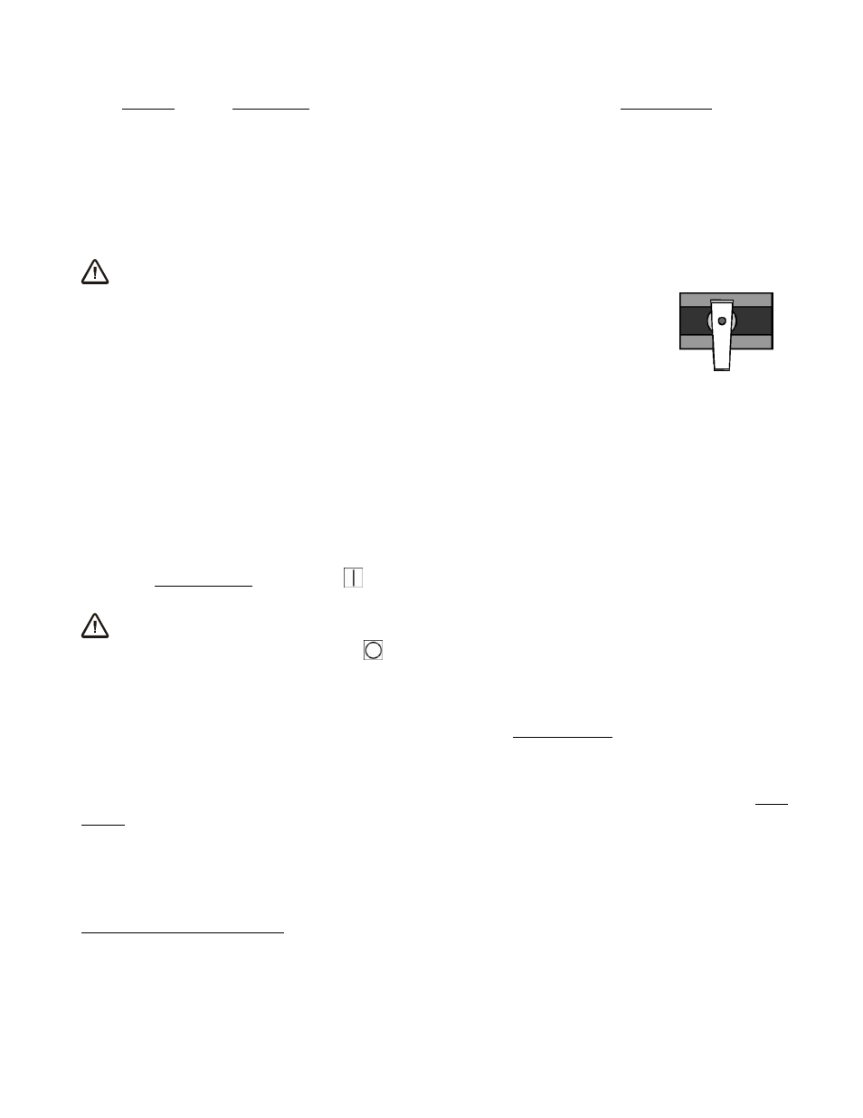
To activate a pad, open the pad shutoff (place valve lever
parallel
with
vacuum line); to deactivate a pad, close the pad shutoff (place valve lever
perpendicular
to vacuum line). To calculate the lifting capacity when some
pads are deactivated, consult the Per-Pad Load Capacity rating (see
SPECIFICATIONS) and multiply by the number of pads currently
activated. Always activate pads in a symmetrical configuration, to keep
the lifter balanced while lifting, and use as many pads as possible for
each load being lifted, to maximize lifting capacity and to minimize load
overhang.
T
O
A
PPLY THE
P
ADS TO A
L
OAD
Powering up the Vacuum Package
Place the power switch in the ON ( ) position (blue indicator light remains illuminated while
power is engaged). The power switch must remain in the ON position while operating the lifter.
5
WARNING: Never turn power off while operating lifter.
Placing the power switch in the OFF ( ) position during lifter operation could result in the
release of the load and possible injury to the operator.
Positioning the Lifter on the Load
Make certain that the contact surfaces of the load and all vacuum pads are free of any
contaminates that could prevent the pads from sealing against the load (see MAINTENANCE:
V
ACUUM
P
AD
M
AINTENANCE
).
The lifter is designed to automatically carry the load in an upright orientation. Center the pad
frame from left to right on the load. Determine which will be the top edge of the load while
lifting, and position the long row of vacuum pads near that edge.
6
This position will maximize
stability while lifting the load. Make sure that all activated pads will fit entirely on the load’s
contact surface (see SPECIFICATIONS: Pad Spread) and that they will be loaded evenly while
lifting (see SPECIFICATIONS: Per-Pad Load Capacity).
5
If a vacuum pump or any other powered component fails to function while the power switch is in the ON position, examine
each circuit breaker (adjacent to power switch) to determine whether it has interrupted the electrical circuit to the component.
Although the operator can reset the circuit breaker, the power interruption may indicate an electrical problem that requires
attention. Correct any deficiency before resuming normal operation of the lifter (see wiring diagram provided).
6
This is the
only row of pads on models MT4HV11FDC and MT6HV11FDC.
CLOSED
PAD SHUTOFF VALVE