Pply the, Ads to a – Wood’s Powr-Grip P211047DC User Manual
Page 10
Rev 12.0/12-12
8
P2-04-DCO: #35114:
T
O
A
PPLY THE
P
ADS TO A
L
OAD
Positioning the Lifter on the Load
Make certain that the contact surfaces of the load and all vacuum pads are free of any
contaminates that could prevent the pads from sealing against the load (see MAINTENANCE:
V
ACUUM
P
AD
M
AINTENANCE
). Center the lifter’s rotation axis to within 2" [5 cm] of the load center,
since off-center loading can cause the load to rotate or tilt unexpectedly (see T
O
R
OTATE THE
L
OAD
E
DGEWISE
or T
O
T
ILT THE
L
OAD
to follow), and it may also damage the lifter.
4
Make sure that all
vacuum pads will fit entirely on the load’s contact surface (see SPECIFICATIONS: Maximum Pad
Spread) and that they will be loaded evenly while lifting (see SPECIFICATIONS: Per-Pad Load
Capacity). Then apply the lifter to the load so that all pads are touching the contact surface.
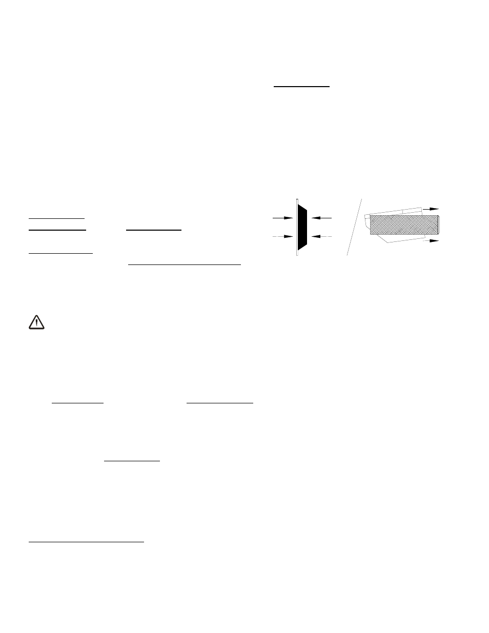
Sealing the Pads against the Load
Firm pressure at the center of the lifter helps the
vacuum pads begin to seal against the load. Pull the
valve handles for both pad channels outward to the
“APPLY” position (power on). This energizes the
vacuum pumps, causing air to be drawn at the pads
immediately. The red low vacuum warning lights also
turn on and remain illuminated until the lifter attains sufficient
vacuum to lift the maximum load weight (see T
O
L
IFT AND
M
OVE THE
L
OAD
: Load Capacity and the
Warning Lights to follow). The valve handles must remain in the “APPLY” position throughout
the entire lift.
WARNING: Keep valve handles in “APPLY” position throughout lift.
Note: If a vacuum pad has been lying against a hard object (as during shipping), it may be
slightly distorted. Although initially it may be difficult to apply the pad to a load, this condition
should correct itself with continued use.
Reading the Vacuum Gauges
Each pad channel is equipped with 2 vacuum gauges, which indicate the current vacuum level in
the 2 circuits of its vacuum system. The operator must read the vacuum gauges on both pad
channels. The
green
range indicates vacuum levels sufficient for lifting the maximum load
weight, whereas the
red
range indicates vacuum levels that are
not
sufficient for lifting the
maximum load weight. Both gauge needles on each pad channel should show a sudden surge
in vacuum as the vacuum pads seal against the load. If it takes more than 5 seconds for the
vacuum level to reach 5" Hg [-17 kPa] on either vacuum gauge, press on any pad that has not
yet sealed.
4
The lifter is designed to handle the maximum load weight (see SPECIFICATIONS: Maximum Load Capacity) when the load’s
center of gravity is positioned within 2" [5 cm] of the lifter’s rotation axis. Occasional loading deviations are permissible,
provided that the operator can maintain control of the load at all times and that the load weight is low enough to avoid damaging
the lifter.
TO APPLY