Warning – Burnham MST396 User Manual
Page 30
30
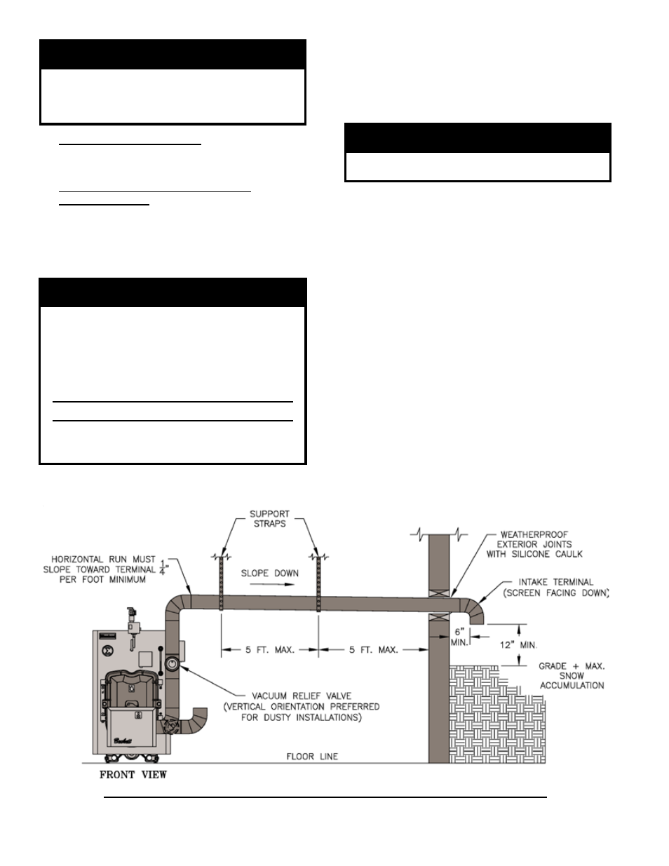
Figure 1: Optional Air Intake Piping Installation - Only Available with Beckett Burner
WARNING
Remove the baffles if there are any signs
of condensation in the chimney or chimney
connector. Consult with your local chimney
professional for recommendations.
E. MINIMUM CLEARANCES
See Figure 2 for details regarding clearances to
combustibles for the boiler.
F. OPTIONAL AIR INTAKE PIPING
INSTALLATION - All air for combustion can be
supplied directly to the burner from outdoors providing
that the criteria for chimney, vent connector and
minimum stack temperature outlined in this section
can be maintained. (ONLY AVAILABLE WITH
BECKETT BURNER). See Figure 17.
WARNING
Using outdoor air in the middle of winter
may result in lower stack temperatures
and chimney degradation. Any signs of
condensate seepage or discoloration at
the base of chimney must be remedied
immediately per the details outlined in this
section.
Do not reduce size of air intake pipe.
Read, understand and follow combustion air
instruction restrictions contained in the Pre-
Installation Section of this manual.
1. General
a. Use 4" dia., single wall galvanized metal pipe
and fittings available at most heating distributors
for air intake piping. Maximum allowable air
intake length is 50 equivalent feet. Each elbow
is equal to 6 equivalent feet.
WARNING
Do not exceed maximum allowable air intake
length.
b. Start at burner. Work toward air intake terminal.
c. Maintain minimum of 1/4 inch per foot slope in
horizontal run to air intake terminal. Slope down
toward air intake terminal.
d. Seal all joints gas-tight, using silicone caulk or
self-adhesive aluminum tape.
2. After determining location, cut a hole in the wall to
accept 4 inch air intake pipe. See Figure 15.
3. Remove the metal knockout in right side of burner
cover. Install Burnham Inlet Air Accessory Kit, Part
Number 611280031.
4. Mount the Vacuum Relief Valve Tee Assembly (P/N
8116268 included with Kit) or 90° elbow into the
burner inlet ring. See Figure 16.
a. Secure with at least three (3) sheet metal screws
evenly spaced around the burner inlet ring.
b. Assemble the vacuum relief valve balance
weight onto the gate. Refer to the vacuum relief
valve manufacturer's instructions.