Operating instructions, Control board functions automatic safety features, Opera tion – Regency Greenfire GFI55 Medium Pellet Insert User Manual
Page 7
Greenfi re Pellet Stove and Insert Owner's Manual
7
OPERA
TION
OPERATING INSTRUCTIONS
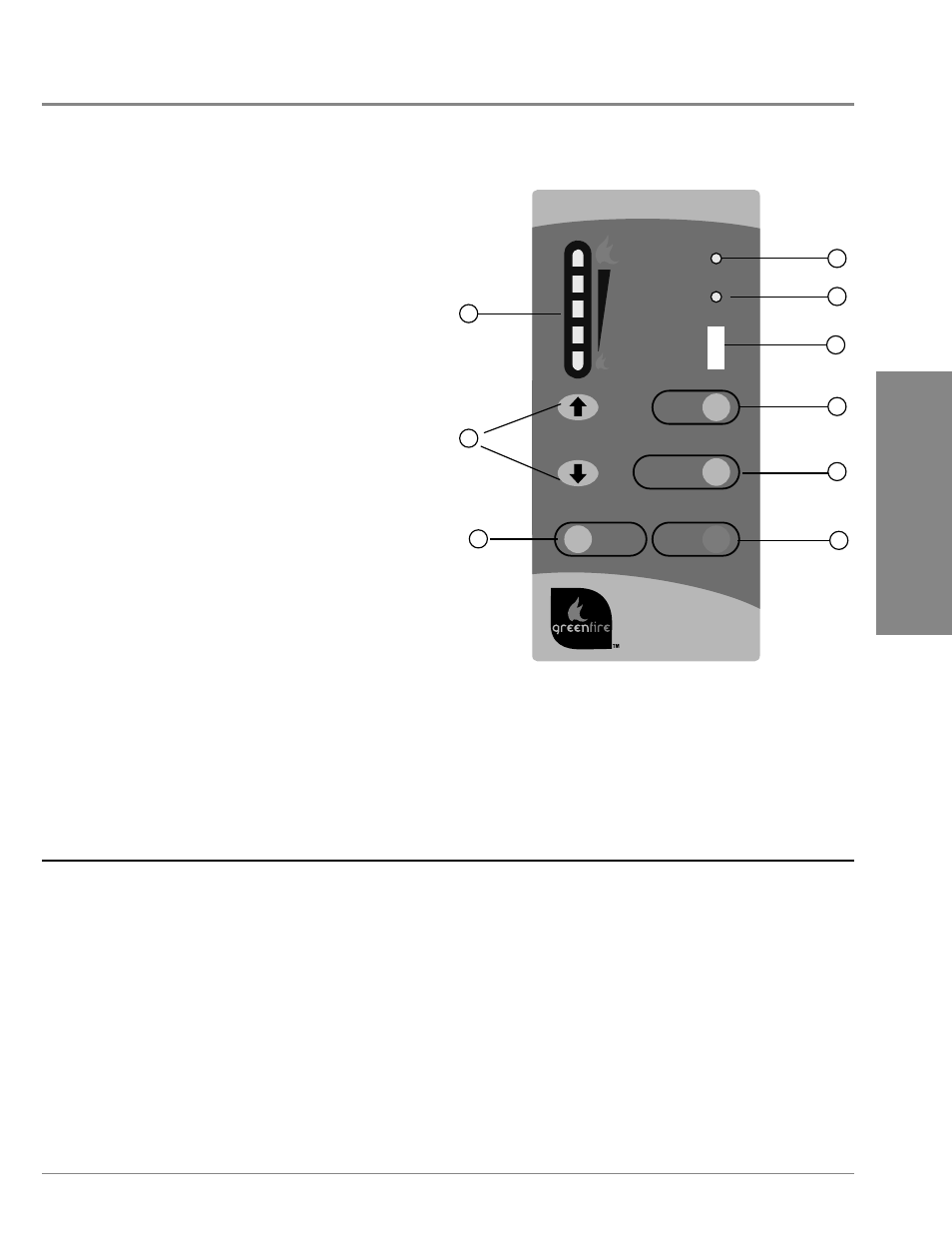
1. AUGER
LIGHT:
This green light will fl ash in conjunction with the auger pulse.
2. MODE
LIGHT:
Responsible for signaling the state of the control board. When the light
is fl ashing the stove is in an automatic start mode or the thermostat
has control of the unit. When the light is solid, the Heat Level Setting
can be altered.
3. THERMOSTAT
SWITCH:
Used to set the unit’s controls to one of three mode settings; Manual,
High/Low, or Auto/Off.
4. FEED RATE TRIM BUTTON:
Used to change the feed rate trims in ¼ second increments for all
feed settings. When this button is pressed, all the light will light up on
the Heat Output Indicator except for the one that shows the current
setting; the default setting is the number 4 light. To adjust the setting
hold the Feed Rate Trim button down and press the Heat Level up or
down buttons to adjust the setting.
5. COMBUSTION BLOWER TRIM BUTTON: Used to change the
Combustion Blower trims in 5 volt increments for all feed settings until
it reaches line voltage. When this button is pressed, all the light will
light up on the Heat Output Indicator except for the one that shows
the current setting; the default setting is the number 2 light. To adjust
the setting hold the Combustion Blower Trim button down and press
the Heat Level up or down buttons to adjust the setting.
6. ON/OFF
BUTTON:
Used to turn the unit On and Off.
7. ROOM AIR FAN ON/OFF BUTTON:
Used to turn convection fan On or Off.
8. HEAT LEVEL ADJUSTMENT BUTTONS:
When pressed, will change the heat level setting of the unit up or down.
9. HEAT OUTPUT INDICATOR:
Shows the present heat output setting.
CONTROL BOARD FUNCTIONS
AUTOMATIC SAFETY FEATURES
A. The stove and insert have a low limit safety switch located on the housing of the exhaust blower. If the exhaust temperatures drop below 120°F
(49°C) the unit will shut down and will be required to go through a full start up procedure again.
The most common cause for this is an empty hopper. This switch should only be by-passed for testing purposes by a technician.
B. The stove and insert have a high limit safety switch located just below the hopper behind the external body panels. If the temperature of this
switch reaches 200°F (93°C), the auger will stop feeding fuel and as the exhaust temperatures drop below 120°F (49°C), the unit will shut
down.
The 200°F (93°C) switch is a manual reset and should only be reset by a service person who can first diagnose the reason for failure.
The two most likely causes are Convection Fan failure or High Limit Switch failure. Either one needs to be properly diagnosed and rectified.
Since this is a safety switch it should never be by-passed for any reason other than the service technician to test the operation.
Figure 3: Circuit Board Control Panel Decal.
GF55-094
ROOM AIR
FAN ON/OFF
HEAT LEVEL
AUTO/OFF
HIGH/LOW
MANUAL
AUGER
MODE
ON/OFF
FEED
TRIM
COMBUSTION
AIR TRIM
1
2
3
4
5
6
8
9
7