Assembly, Step 1, Step 2 – Briggs & Stratton 37641401 User Manual
Page 4
MODEL 37641401 - 04
PeCo
4
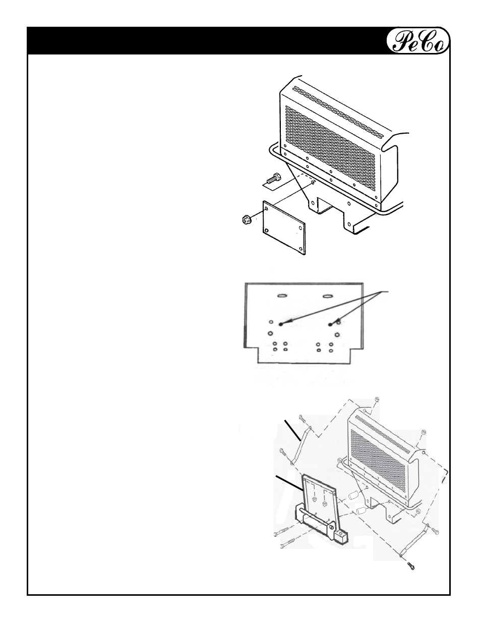
ASSEMBLY
STEP 1:
FIG. 1-1
DESIGNATION OF
HOLES ON THE
MOUNT PLATE
HOLES TO
MOUNT TO
TRACTOR
Remove plate on rear of mower as shown.
Redrill top two holes for a 3/8"-16 hex bolt
to mount Mount Frame onto mower frame.
STEP 2:
Use (2) 3/8"-16 x 2" (#K1208) and (2)
3/8"-16 flange nuts (#K1215) to secure
Mount Plate (A) to mower frame. Use (2)
1" spacers (#S0138) between Mount
Plate (A) and mower frame. Place (1)
Bracket (B) on each side of Mount Plate
(A). Use (1) 3/8"-16 x 3/4" hex bolt (#K1190)
and (1) 3/8"-16 flange nut (#K1215) to
mount each Bracket. Use existing bolts
from mower frame to mount Bracket (B)
to mower. Use figure 1-1 to place bolts.
MOWER
FRAME
A
B
See also other documents in the category Briggs & Stratton Gardening equipment:
- 1695284 (14 pages)
- Axion 7800378 (18 pages)
- SNAPPER 7800757 (24 pages)
- INTEK AND QUANTUM 120000 (20 pages)
- 277110TRI (28 pages)
- 196400 (76 pages)
- 7800189 (20 pages)
- 123K00 0134 (13 pages)
- Easy start R5055H 5.5 HP (28 pages)
- 5900619 (52 pages)
- SNAPPER 7800752 (24 pages)
- Harrier 41 (36 pages)
- SNAPPER LT-125 (48 pages)
- NSPV21675 (22 pages)
- 445700 (12 pages)
- 406700 (20 pages)
- 21C200 (12 pages)
- 5901070 (98 pages)
- HERITAGE TRACTOR 131F (36 pages)
- HIDRO DRIVER ZTR 5900682 (72 pages)
- 20G400 (12 pages)
- SNAPPER GT23540 (58 pages)
- 76065 (1 page)
- SP21 (30 pages)
- 205300 (20 pages)
- FM3300 (20 pages)
- 1628 (36 pages)
- SNAPPER 7085625 3013523BVE (56 pages)
- 1694561 (4 pages)
- 1695353 (16 pages)
- MOWER (62 pages)
- 5900683 (50 pages)
- 94200 (20 pages)
- 1695354 (18 pages)
- 7800692 (36 pages)
- Ram Mag 50 / 968999651 (88 pages)
- Snow Series (24 pages)
- 5900664 (19 pages)
- Series 410 thru 420 (16 pages)
- Electric Lawnmower (28 pages)
- 5900703 (16 pages)
- 21A400 (16 pages)
- AA0201 (9 pages)
- MS-5158-5/03 (10 pages)