Ultragraph digital deq1024, Control elements – Behringer DEQ1024 User Manual
Page 6
6
ULTRAGRAPH DIGITAL DEQ1024
2. CONTROL ELEMENTS
Use the 45-mm EQ faders to increase or decrease any
one of the 31 frequency bands. Each fader has its own
red LED.
Use the FADER RANGE switches to regulate increasing/
decreasing in three different levels: +12/-12 dB (green
LED), +6/-6 dB (green LED) and 0/-24 dB (yellow LED). The
last option is well suited for eliminating feedback
frequencies, since you can select a very pronounced
lowering of a specific frequency range (-24 dB).
+
Each switch on your DEQ1024 (with the exception of
CONFIG and CLOCK) has its own LED that lights up
when the respective function is activated.
+
All settings you implement always affect both
channels of your DEQ1024.
The DEQ1024 features an automatic FEEDBACK
DESTROYER.
Activating the FEEDBACK DESTROYER:
When you press the ON/OFF switch (yellow LED lights
up), the feedback destroyer scans the audio signal for
feedback frequencies. As soon as one or more frequencies
show feedback, the red LED of the RESET (HOLD) switch
lights up. The affected frequencies are then automatically
lowered. In addition, your audio program is constantly
scanned for new feedback frequencies, and feedback is
destroyed as it comes up. This makes sense for
microphones that are in constant motion during a stage
performance (e. g. vocal microphones), where feedback
may arrise constantly.
Deactivating the search function (feedback
suppression remains active):
If you now press the ON/OFF switch for a second time, the
feedback analysis stops. Those frequencies emitting
feedback will continue being lowered (RESET (HOLD) LED
is still on). This procedure is well suited for stationary
microphones, such as drum microphones. To start the hunt
for feedback again, hit the ON/OFF switch once again.
Displaying the feedback frequencies:
If you briefly (for approx. 2 seconds) depress the RESET
(HOLD) switch, the feedback frequencies that the DEQ1024
was able to find will be indicated on the respective fader
LEDs. If no feedback occurs, the LEDs will stop being lit up
for roughly 2 seconds.
Deactivating the FEEDBACK DESTROYER:
If you hold the RESET (HOLD) switch depressed for a few
seconds, the filter settings are reset (RESET (HOLD) LED
dies out) and the FEEDBACK DESTROYER is deactivated.
If you press the FB INDICATOR switch (green switch
LED lights up), the FBQ feedback detection system is
activated. The frequency (or the frequencies) that cause
feedback are now shown in the form of a brightly shining
fader LED. All other LEDs are dimmed. Simply lower
somewhat the pertinent frequency range until feedback is
no longer present and the LED dies out.
By displaying the intensity of individual frequency ranges,
the feedback recognition system also functions as an audio
analyzer.
+
Please keep in mind that the FB INDICATOR only
shows the intensity of the individual frequency
bands. Not every frequency that is present
automatically causes feedback.
+
FEEDBACK DESTROYER and FB INDICATOR function
independently from one another and can be
activated simultaneously. Please bear in mind: when
in 96-kHz mode, FEEDBACK DESTROYER and
FB INDICATOR are not available!
When you keep the PINK NOISE switch depressed for a
few seconds, the internal pink noise generator of your
DEQ1024 is activated (red switch LED lights up) and the
volume level of the test signal is gradually increased as
long as the switch remains depressed (the level is shown
on LEVEL METER
). Briefly pressing the PINK NOISE
switch once again deactivates the function.
PINK NOISE
Room resonance and the transmission characteristics of
your P.A. system naturally lift certain frequencies while
lowering others. Pink noise is a neutral signal that can be
played back over the P.A. system in order to measure
these room characteristics. One such measurement of the
frequency response with a special measurement
microphone (e. g. BEHRINGER ECM8000) coupled to a real-
time analyzer (integrated in the BEHRINGER ULTRACURVE
PRO DEQ2496) delivers the foundation for setting up the
equalizer. Boosted frequencies can be lowered by means
of your equalizer, while frequencies that are too weak can
be boosted, and a nearly linear playback is achieved.
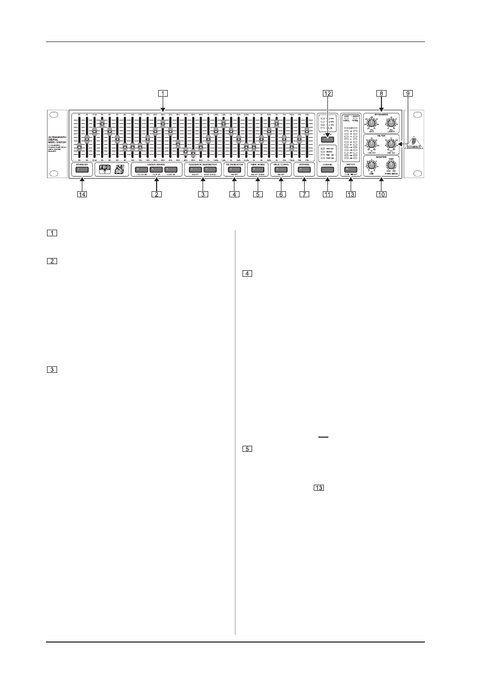
2. CONTROL ELEMENTS
2.1 Front panel
Fig. 2.1: Front panel control elements