Inst-602rf-cul.pdf, Test unit annually, Power supply specifications – SDC 602RF User Manual
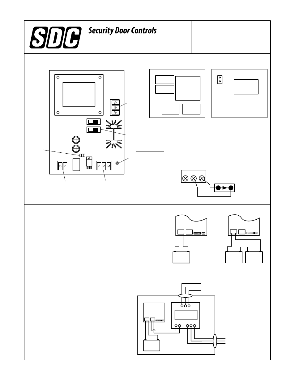
Page 2: Component locations, Model 602rf-cul, Cover, Main system on-off
P:\INSTALLATION INST\Power Supplies\INST-602RF-CUL.vsd Rev B 04-13
SPECIAL APPLICATIONS POWER SUPPLY
INSTALLATION INSTRUCTIONS
MODEL 602RF-CUL
801 Avenida Acaso, Camarillo, Ca. 93012
(805) 494-0622 • Fax: (805) 494-8861
www.sdcsecurity.com • E-mail: [email protected]
POWER SUPPLY SPECIFICATIONS
Input Voltage: 115 VAC @ 60hz
Input Current: 0.8 amps Max.
Output Voltage: 12/24VDC (Special Applications)
Burglary Use:
Output Voltage Ranges:
12 V Operation: 9.2 – 12.0 VDC
24 V Operation: 21.2 – 24.0 VDC
Output Current: 1.0 amps
Ripple Voltage: 0.05 Volts Max.
Battery Charger Max. Current: 0.25 amps
Maximum recommended battery size: 4ah
Recommended Battery: SDC Model RB12V4
(Replace batteries every 3 years)
To determine standby battery capacity refer to
Battery Discharge Table (INST-BDT).
Suitable Uses:
Electric Lock Power Supply
Access Control Power Supply
TEST UNIT ANNUALLY
BATTERY 1
4ah
POWER
SUPPLY
BOARD
BATTERY 1
4ah
COMPONENT LOCATIONS
STANDARD BOX
CONTROL
MODULE
CONTROL
MODULE
MODEL 602RF-CUL
AC VOLTAGE
INPUT
VOLTAGE SELECT
SWITCHES
BATTERY INPUT
TERMINALS
MANUAL
RESET
SYSTEM STATUS
YELLOW – SYSTEM OK
RED – ON BATTERY PWR
GREEN – NO DC OUTPUT
VOLTAGE OUTPUT
TERMINALS
COVER
BATTERY MONITOR LEDS
GRN = AC
RED = BATTERIES
ORG = NO/LO BATTERY
MAIN SYSTEM ON-OFF
Min. Switch or
Contact Ratings
100mA @ 30VDC
+
_
C
Master ON/OFF
Switch (N/C)
12VDC
+
_
+
_
12VDC
+
_
+
_
24 Volt Mode Battery
Connections
Monitor Board
12VDC
+
_
+
_
+
_
12 Volt Mode Battery
Connections
Monitor Board
Note: Power limited
cable must maintain a
1/4” or more of spacing
from battery cables or
primary power wires.
602RF-CUL
Battery
+
C
_
HIGH
VOLTAGE
INPUT
POWER LIMITED
CLASS 2 OUTPUT
+
_
+ _ + _
+
_