Schwank STSp-CANADA User Manual
Page 15
SP-MSTP-AC-15A
STS-p Manual
RD: DEC, 2003
RL:15
KH
Page 11
TABLE 4
MODEL
TURBULATOR LENGTH
(IF REQUIRED)
STS-p 200-70/60/50
10’
STS-p 175-70/60/50
10’
STS-p 155-60
not required
STS-p 155-50
not required
STS-p 155-40
10'
STS-p 130-50
not required
STS-p 130-40
10'
STS-p 130-30
14'
STS-p 110-50
not required
MODEL
TURBULATOR LENGTH
(IF REQUIRED)
STS-p 110-30
14'
STS-p 80-40
10’
STS-p 80-30
14'
STS-p 80-20
14'
STS-p 60-30
14’
STS-p 60-20
14'
STS-p 45-20
5’
STS-p 45-10
5’
STS-p 110-40
10'
Where required the STS-p Series Heaters will be supplied with the turbulators, factory
installed into the end tube(s) of the system configuration.
NOTE:
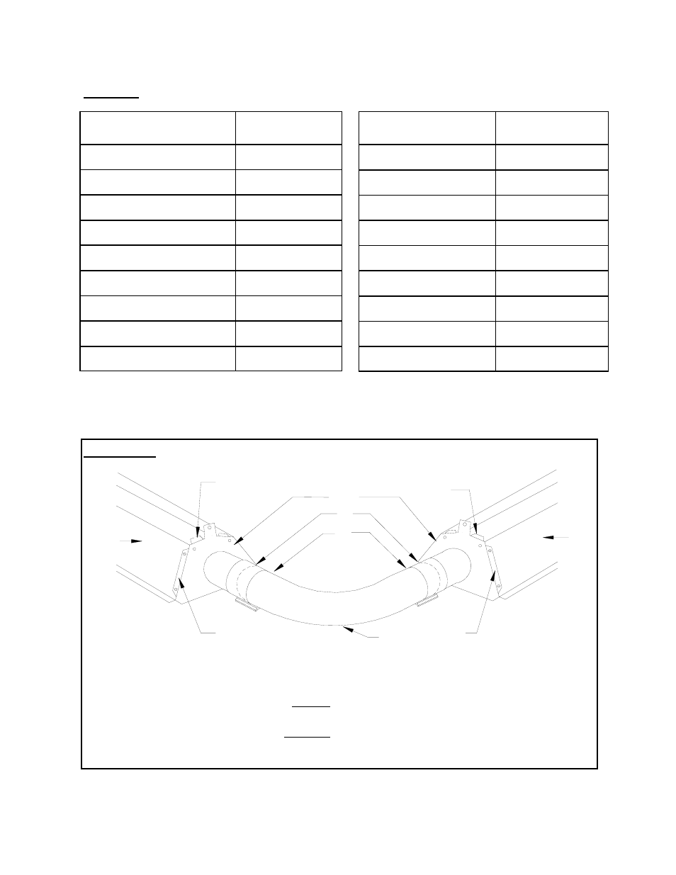
FIGURE 12 PLATE HANGER/ELBOW INSTALLATION
5 90
0
(shown) or 180
0
Elbow
6 Tube Coupler
7 Point at which Swaged tube is fully
inserted into elbow and Swaged end of
elbow is fully inserted into tube.
1 End-Plate-Hangers
2 Focus Shield Reflectors
3 End-Plate-Hanger Flange OVER
Reflector
4 End Plate Hanger Flange UNDER
Reflector
1
2
2
3
3
4
4
5
6
7