Warning – Schwank premierSchwank IQ User Manual
Page 42
42
STS-JZ-F / IQ-F I&O Manual
IM101220
RD: AUGUST 2014
RL: 18A
Flame Fault
If at any time the main valve fails to close completely and maintains a flame, the full time flame
sense circuit will detect it and energize the combustion blower. Should the main valve later
close completely removing the flame signal, the combustion blower will power off following the
optional post purge period.
Fault Conditions
The LED will flash on for 1/4 sec-
ond, then off for 1/4 second during
a fault condition. The pause be-
tween fault codes is 3 seconds.
MOUNTING AND WIRING
The Series 35-61 is not position sensitive and can be mounted vertically or horizontally. The
case may be mounted on any surface with #6 sheet metal screws. All wiring must be done in
accordance with local and national electrical code. Refer to wire diagram page 35 when con-
necting the Series 35-61 to other components in the burner.
The Series 35-61 DSI Control uses voltages
of shock hazard potential. Wiring and initial
operation must be done by a qualified service
technician. The control must be secured in an
area that will experience a minimum of vibra-
tion and remain below the operating tempera-
ture of 160ºF. All connections should be
made with UL approved 105ºC rated 18
gauge, stranded, .054 thick insulated wire.
Refer to wire diagram page 35 when con-
necting the Series 35-61 to other compo-
nents in the burner.
CAUTION:
Label all wires prior to disconnection when servicing controls. Wiring errors can cause improper
and dangerous operation. A functional checkout of a replacement control is recommended.
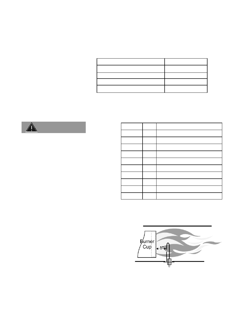
PROPER ELECTRODE LOCATION
Proper location of the electrode assembly is impor-
tant for optimum system performance. The electrode
assembly should be located so that the spark gap is
inside the flame envelope about 1 inch (2.5 cm) from
the base of the flame at the burner cup.
Electrodes should have a gap spacing of 3/16” (0.188” ± 0.031” or 4.76 mm ± 0.81 mm). If this
spacing is not correct, the assembly must be adjusted or replaced. DO NOT adjust the curved
igniter/sensor prong. Adjust/bend only the ground prong (also see next page).
Error Mode
LED Indication
Internal Control Failure
Steady on
Air Flow Fault
1 flash
Flame with No Call for heat
2 flashes
Ignition Lockout
3 flashes
WARNING
TERMINAL
TH Thermostat
Input
PSW
Pressure Switch Input
V1
Valve Power (MV)
IND
Inducer Blower Output
L1
120/240 VAC Input (Hot)
24 VAC
24 VAC Supply to Processor
V2 Valve
(MV)
GND
Valve & System Ground
Spark
Spark & Local Flame Sense
NC
Alarm (Not used)
DESIGNATION
SPADE
1/4”
1/4”
1/8”
1/4”
-
1/4”
1/4”
1/8”
1/8”
1/4”