S&S Cycle EZFI User Manual
Page 3
3
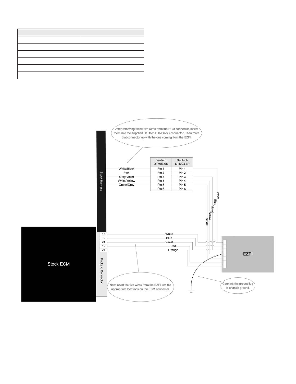
9- Insert the five EZFI™ wires into the ECM connector per Table 3 and confirm that all the wiring matches the wiring diagram in Figure 1.
10- Install the clear retainer onto the ECM connector and close the connector. Use a zip tie for strain relief of the ECM connector wires. Reconnect
the harness to the ECM.
11- Reconnect the negative terminal of the battery, and with the black wire with the ground lug from the EZFI. If the EZFI’s ground lug will not reach
the battery, find a suitable grounding point on the frame to bolt it to.
12- Reinstall the electrical caddy (Harley Davidson® Dyna™ installation only), side covers and seat.
Table 3 - EZFI Wire Colors in ECM Connector
EZFI Wire Color
ECM Pin #
Blue
3
White
13
Red
19
Orange
21
Violet
24
EZFI OPERATION
The EZFI system is simple to operate. A 10 position mode switch allows you to select which RPM and throttle range to tune. The 10 operating modes
are listed in Table 4. The display is turned off in Mode 0.
The Value LED displays the adjustment percentage for the selected range. The indicated number is the percent fuel being added (positive) or taken
away (negative) from the base pulse width. The small LED is lit when the adjustment is negative, which means the EZFI is leaning the mixture out
in that range.
The Up and Down buttons raise or lower the fuel adjustment for the selected operating range.
Advanced tuning of both front and rear fuel maps is possible when our EZTune software is used in conjunction with our S&S® Super Stock® diagnostic
cable. These are available separately.
Figure 1