S&S Cycle EZFI User Manual
Page 2
2
Thank you for choosing S&S® Cycle’s EZFI™ system. EZFI works in conjunction with all stock 2001-2007 H-D® ECMs. EZFI is able to add or remove fuel
to match the precise fueling needs of a wide variety of engines with performance modifications.
WhAT YOU’LL NEED
10 mm wrench
Phillips screwdriver
3/16 hex key and T30 Torx
(Dyna installation only)
Side cutter
Small flat screwdriver
INSTALLATION
6- Insert the supplied orange wedge lock into the Deutsch connector.
7- Find a suitable location for the EZFI module. On Touring models, the EZFI can be piggybacked on top of the stock ECM. On Dyna models, the
EZFI can be located in the space to the right of the electrical caddy with the wires routed through the caddy. Use a zip tie or Velcro® to secure
the EZFI.
8- Plug the Deutsch connector assembled in step 6 into the EZFI’s mating Deutsch connector. Verify the wire colors across the six pin Deutsch
connector. They should line up per Table 2.
CAUTION
To protect against shock and accidental start-up of the engine, disconnect the negative battery cable. Inadequate observation of safety precautions
could result in serious injury or death.
1- Disconnect the negative battery terminal.
2- Remove the right side cover (Touring models) or seat (Harley-Davidson® Dyna™ and Softail® models) to gain access to the ECM.
2a- If installing on a Dyna, also remove the left side cover and electrical caddy. Refer to the service manual for further directions on accessing the
ECM.
3- Open the gray ECM connector and remove the clear retainer.
4- Remove the following wires from the ECM connector by using a small screwdriver to gently lift the retaining tabs while pulling on the wire. Wire
colors may vary, so check that you are removing wire from the proper position.
Position 3 - Pink – Tachometer (may not be present on some models)
Position 13 - White/Black - Switched Ignition Power
Position 19 – Green/Gray – Rear Injector
Position 21 - White/Yellow – Front Injector
Position 24 - Gray/Violet – Throttle Position Input
5- Insert the wires removed in step 4 into the supplied six position Deutsch® connector per Table 1.
Table 1 - Wire Insertion Guide
ECM Pin #
Stock Wire Color
Deutsch Pin #
3
Pink
2
13
White/Black
1
19
Green/Gray
5
21
White/Yellow
4
24
Gray/Violet
3
Table 2 - Deutsch Connector Wire Colors
Stock Wire Color
Deutsch Pin #
EZFI Wire Color
White/Black
1
White
Pink (optional)
2
Blue
Gray/Violet
3
Violet
White/Yellow
4
Yellow
Green/Gray
5
Green
Not Used
6
Not Used
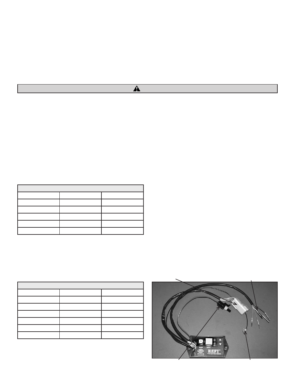
Picture 1
Deutsch Connector
Wires to ECM Connector
Data Link (optional)
Ground Lug