S&S Cycle Degree Wheel Kit PN 53-0020 User Manual
Page 3
During disassembly breather timing should be checked and
set to:
Breather valve opens at 20˚ to 25˚ ATC
Breather valve closes at 85 to 90 ABC
To check existing breather timing set degree wheel to TC 0˚ mark
with front piston at TDC. Perform checks with pushrods and cam
cover removed.
To set breather timing to above specs during engine rebuild
perform following steps:
1.
Engines 1957 to 1971 - We strongly recommend purchase of
1972 and later pump breather gear, part #26331-72, and
corresponding gear retainer lock ring, part #11002. These
parts are used in place of early pump breather gear, part
#26331-60, because slot in early gear is wider and makes
modification of pump body too difficult to obtain desired
results. To use later parts install scavenger gear, part
#26315-62, with flat side of gear facing retainer lock ring.
2.
Assemble engine to point of oil pump installation.
3.
Place degree wheel on sprocket shaft and set to TC 0˚ mark
with front piston at TDC.
4.
Turn pump gear counterclockwise until slot in gear aligns
with slot in pump body.
5.
Place .002” shim in opening and reverse gear until shim is
held tight between body and gear.
6.
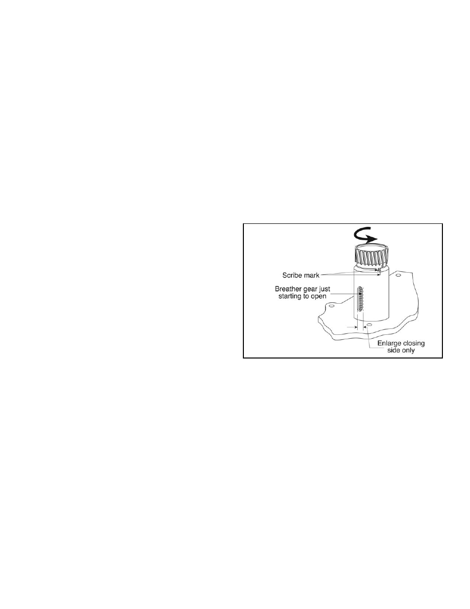
Scribe mark across pump gear sleeve and pump body at small
timing notch on top edge of body. See Figure B. Because
pump gear sleeve is very hard and difficult to scribe mark, it
may be advantageous to coat top portion of sleeve just
below teeth with Dykum
®
Blue.
7.
Install and time pump using normal assembly procedure. Do
not final tighten oil pump mounting bolts.
8.
Rotate flywheels to 25˚ ATC mark. Be sure oil pump drive
gear is firmly butted against shoulder on pinion shaft. If
scribe mark on pump gear is to left of scribe mark on body,
grind material off engine side of pump drive gear to allow it
to move farther onto shaft until scribe marks align. If scribe
mark is to right, shim between pump drive gear and
flywheel assembly until marks line up. Big twin cam thrust
washers, part #25550-36, can be used as shims, but are
marginal because they do not fit well on pinion shaft. If you
are not satisfied with fit, you may machine your own shims
like we do.
9.
Rotate flywheels to 85˚ ABC mark. Make second scribe
mark on pump gear sleeve that lines up with first scribe
mark on body.
10. Remove pump and carefully grind or file side of slot towards
cam cover in body (closing side only) until slot closes when
second scribe mark on sleeve and first mark on body line up.
11. Thoroughly clean and final assemble oil pump in crankcases.
12. Place oil pump drive gear on pinion shaft, and time pump in
normal fashion. If material was removed from flywheel side
of oil pump drive gear, it will be necessary to shim between
pump drive gear and pinion gear. Pinion gear must be flush
with or extend out slightly past splines on pinion shaft when
installed tight against pump drive gear.
13. Check clearance between pinion gear and cam cover
bushing. Clearance must be .005”. Use Plasti-gauge or
whatever method you choose to determine clearance. Shim
on outer side of pinion gear to obtain .005” clearance.
Harley-Davidson
®
shims, part #18268-48, are .015” thick each
and may be used for this purpose.
*All reference to Harley-Davidson
®
part numbers is for
identification purposes only. We in no way are implying that any
of S&S
®
Cycle’s products are original equipment parts or that they
are equivalent to the corresponding Harley-Davidson
®
part
number shown.
3
Figure B