S&S Cycle Degree Wheel Kit PN 53-0020 User Manual
Page 2
General Information
Degree wheels have many uses. The more important ones
are setting ignition timing, checking crankcase breather
timing and checking cam timing.
The S&S
®
degree wheel assembly adapts to fit most any 45˚
v-twin engine by combining one or more of the special
collars supplied in each kit. Once a proper combination is
selected, the wheel is secured with a sprocket nut or with
the clamping screw on the degree wheel.
Degree Wheel Divisions and Terminology
Degree wheel references encountered are listed below.
After Top Center (ATC) = Top Center (TC) (0˚) clockwise
to 90˚
Before Bottom Center (BBC) = 90˚ ATC clockwise to
Bottom Center (BC) (0˚)
After Bottom Center (ABC) = BC (0˚) clockwise to 90˚
Before Top Center (BTC) = 90˚ ABC clockwise to TC (0˚)
Ignition and Crankcase Breather Timing Piston
Positioning
Most ignition timing and crankcase breather timing is done using
front cylinder. To use S&S degree wheel:
1.
Determine highest point of piston travel (Top Dead Center -
TDC) for front cylinder and rotate flywheels so piston is in
that position.
2.
Clamp degree wheel on sprocket shaft so pointer lines up
with with Top Center (0˚) mark. (Most S&S flywheels have a
Top Dead Center front cylinder (T/F) timing mark to indicate
highest point of front piston travel. When mark is positioned
in center of timing hole, front piston is at TDC.)
To locate TDC for rear cylinder by using front cylinder:
1.
Position front cylinder at TDC.
2.
Clamp degree wheel on sprocket shaft so pointer lines up
with with 45˚ ATC mark.
3.
Rotate flywheel assembly with degree wheel clamped in
place so pointer lines up with Top Center (0˚) mark. Rear
cylinder is now positioned at TDC.
Ignition Timing Flywheel Marks
Ignition usually occurs before piston is at TDC. All ignition timing
are positioned Before Top Center (BTC).
See the appropriate manual for timing specifications.
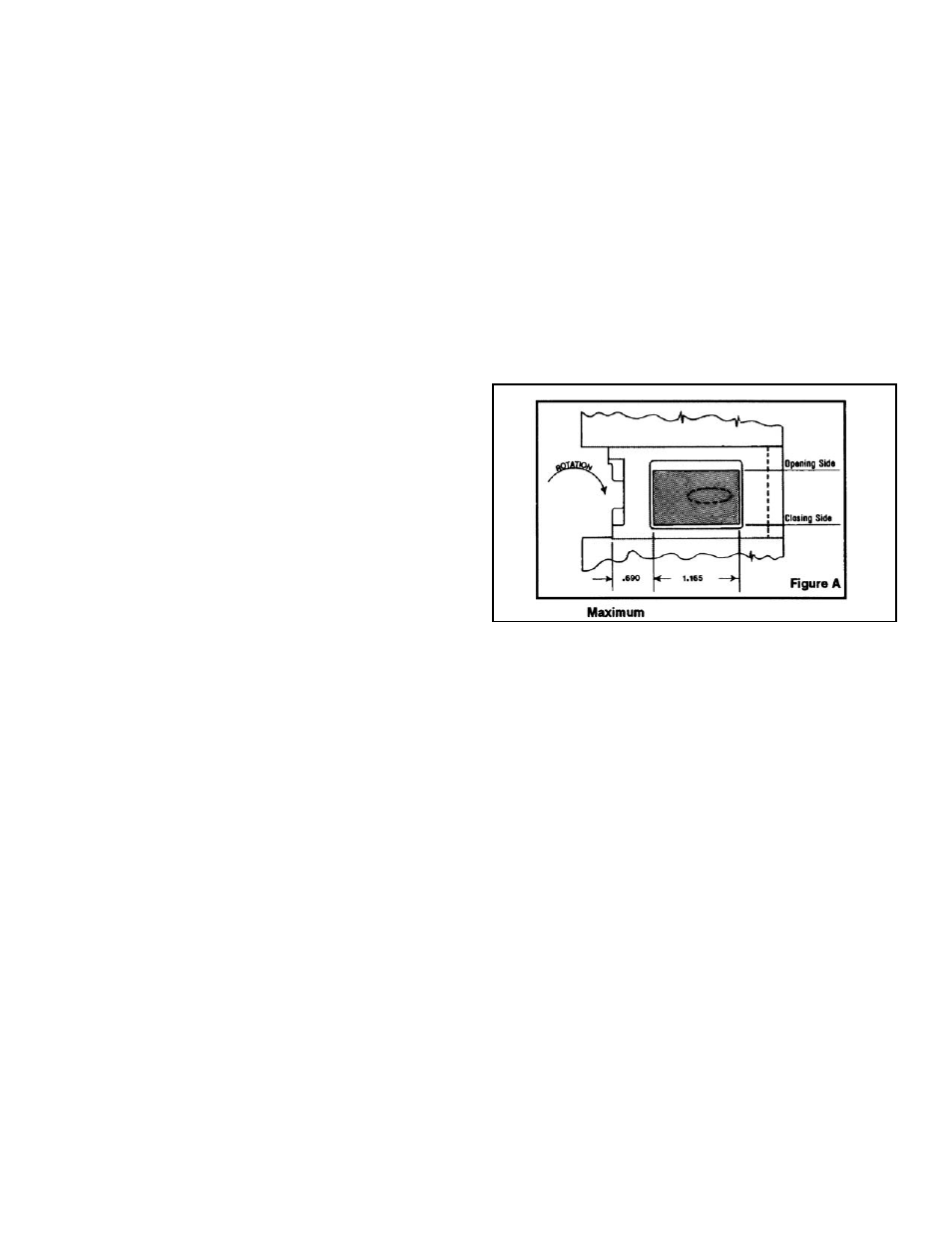
Crankcase breather timing for big twin engines
The crankcase breather timing on all big twins should be
checked. Engines prior to 1980 require checking especially so,
because the normal breather opening is a rough cast elliptical
hole. This hole must be filed or ground to a rectangular
shape: width and length should not exceed original
dimensions. On all engines opening and closing sides and
.690” dimension (See Figure A) should then be checked
against specifications listed and filed if necessary.
This data is presented to maximize crankcase breathing
efficiency which will help an engine perform better and cleaner.
Set degree wheel to TC 0˚ mark with front piston at TDC.
Perform checks before engine is disassembled with pushrods
and cam cover removed.
Maximum
Breather opens 10 degrees BTC
Breather closes 75 degrees ABC
Minimum
Breather opens 10 degrees ATC
Breather closes 55 degrees ABC
We recommend using maximum specifications in competition
engines. In most street engines if specs are within opening and
closing tolerance ranges, do not remove any additional material.
1957 to -‘77 Harley-Davidson
®
Sportster
®
model
Breather Timing
Examination of some street engines has shown that breather
timing varies from engine to engine. This is because positioning
of the flywheel assembly in the crankcases changes the location
of the pump drive worm gear on the pinion shaft and how it
engages the oil pump gear.
2
Figure A