S&S Cycle Mechanical Compression Release PN 90-4925 User Manual
Page 4
4
C. Adjust Cables
NOTE - Adjustment of the actuating cables is critical for proper operation of S&S® manual compression releases. Failure to adjust cables correctly may
result in damage to the compression release and the engine.
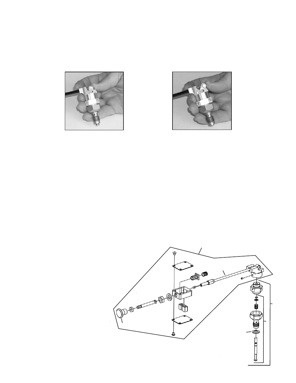
1. Make sure that both compression release valves are closed. Lightly push the cam against the plunger. If the compression release valve is
open, the cam will be in a vertical position when it contacts the plunger. If the cam is not in a vertical position when the cam is in contact
with the plunger, the valve is closed. See Pictures 11 and 12. If one or both valves is open, it will be necessary to remove cam assemblies
and close valves by pulling the plungers up with pliers.
2. Adjust the free play in the cables.
a. Make sure that the compression release valves are both in the closed position, and the cable is in the normal position.
b. Turn the adjusters out of the activator housing just enough to remove free play in the cable. Do not make the cable tight. There
should be no pressure on the plunger.
c. Screw the cable adjusters one half turn into the activator housing to give the cables a small amount of free play. A small amount
of movement should be felt if the activator cam is pushed by hand. This clearance is required so that there is no pressure on the
plungers except when the activator knob is pulled. It is very important to insure that the valves are allowed to close freely at all times.
3. After cables have been adjusted, tighten cable adjuster jam nuts against activator housing to lock adjusters in place.
4. Re-install rocker covers, pushrods, and rocker arms according to standard assembly procedures. Consult appropriate manuals as needed.
If adjustable pushrods are used, they should be readjusted. Reinstall gas tank and any other components removed during installation of
compression releases.
D. Operation
When the activator knob is pulled, the compression release valves are opened and are held open by the detent assembly. The knob is released
and returns to its normal position. When the engine turns over, the compression release valves allow some of the cylinder pressure to bleed off
into the exhaust port. The reduced cylinder pressure makes it easier for the starter to turn the engine. When the engine starts, the increased
cylinder pressure from combustion automatically closes the compression release valves. All cylinder pressure is then contained in the
combustion chamber and the engine runs normally with full compression.
Picture 11
Picture 12
1
2
3
4
5
6
Replacement paRts FoR manual compRession Release
1.
Compression release assembly ......................................90-4920
2.
Valve assembly, compression release, manual ..............90-4921
3.
Washer, compression, 14mm .......................................50-7094
4.
Cable assembly, compression release manual ...............90-4919
5.
Activator assembly, compression release, manual ......90-4932Z
6.
Knob, 1" x 1⁄4 -20, black plastic .................................. 50-8700-S
1" x 1⁄4 -20, polished billet aluminum ...........................50-8701
7.
S&S two piece comp. release socket kit (Not Shown) ....53-0045
8.
S&S compression release hole plug (Not Shown) ..........90-4916