S&S Cycle Mechanical Compression Release PN 90-4925 User Manual
Page 3
3
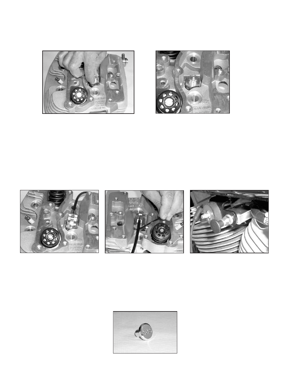
7. Apply a small amount of Loctite® 272 (red) to the threads of the detent assembly body.
8. Push the detent assembly over the plunger and thread into valve assembly until hand tight. See Picture 5. Make sure that no Loctite is
allowed to contact the plunger. Torque the detent assembly into the valve assembly to 28-30 ft-lb. Using a pliers, carefully pull the valve
plungers up to close the valves. The valves must be closed to properly adjust the cables. Plunger protrusion above detent assembly will be
approximately .200” if the valve is closed, and .100” when valve is open. See Picture 6.
B. Install Cam and Cable Assemblies
1. Remove the 10-24 set screws from the cam assemblies and place a small drop of Loctite® 242 (blue) on the threads.
2. Reinstall set screws in the cam assemblies.
3. Place cam assemblies over the plungers of the detent assemblies. Index the cam assemblies and cables so the cables lay toward the intake
manifold, but are not contacting the cylinder heads. See Picture 7.
4. When cam assemblies are positioned correctly, tighten set screws to prevent them from moving. See Picture 8.
5. Install activator assembly in stock choke bracket. See Picture 9. If bracket has a mounting hole instead of a mounting notch, it will be
necessary to remove the pull knob, lock washer, and jam nuts in order to install activator assembly.
NOTE – Because of the variety of chassis and bracket designs, the mounting of the activator assembly may be somewhat different from that shown in
Picture 9. It may be necessary to fabricate a different bracket or to modify the existing bracket.
6. With the activator assembly in position in the mounting bracket, install the 3⁄8” lockwasher and jam nut if removed, and tighten jam nut
firmly. Install knob and 1⁄4” jam nut if they have been removed. If billet knob is used, rotate to desired position and turn jam nut against knob
to lock it in place.
NOTES
Do not apply any type of thread locker to the 3⁄8” or 1⁄4” jam nuts or to the knob. Doing this will make disassembly extremely difficult and may cause
•
damage if parts must be disassembled.
S&S offers an optional polished billet aluminum knob which is installed in the same manner as the black plastic knob.
•
See Picture 10. (Polished billet
pull knob is available for a custom look.
Picture 5
Picture 6
Picture 7
Picture 8
Picture 9
Picture 10