S&S Cycle Standard and Easy Start Chain Drive Camshafts for Harley-Davidson Twin Cam 88 Engines 1999–2006 Big Twin, except 2006 Dyna models User Manual
Page 5
5
All reference to Harley-Davidson part numbers is for identification purposes only. We in no way are implying that any of S&S Cycle’s products are original equipment parts
or that they are equivalent to the corresponding Harley-Davidson part number shown.
NOTE: It is not necessary to remove oil pump from engine to complete
installation. However, it is highly recommended that new o-rings be
installed when ever the oil pump is loosened or disturbed. The cost of
replacing them at this point is minimal, but will be considerable if the engine
must be disassembled again to replace them.
12. Remove screws that secure bearing retainer to support plate and
remove retainer from plate.
13. Support cam support plate on table of hydraulic press. Using
camshaft remover/installer tool H-D® #43644, remove stock cams
and bearings from plate. Mark chain with magic marker to indicate
direction of travel. See Picture 7, next page.
Do not attempt to remove cams from bearings while bearings are
in bearing plate. Cams and bearings must be removed from plate
together. See Picture 7, next page.
Cam and bearings may press out easily. Use care to support cams so
they don’t unexpectedly fall to the floor.
NOTES: Bearings are usually damaged during removal and should not be
reused. If S&S® Cam Installation Kit (33-5175) is not used, new cam bearings
should be obtained from other source and installed with new cams.
• Check primary and secondary cam shoes for wear and/or damage.
Do not re-use either shoe if more than 1⁄2 the shoe thickness is worn, or
if there is any evidence of melting, burning, or cracking.
• Replacement shoes are installed per appropriate Harley-Davidson®
service manual.
• If upgrading from keyed rear camshaft to splined rear camshaft,
further steps require use of 2000 and up splined rear sprocket and
spacer. Spacer style used with keyed cams is not compatible with
splined cams. Spacers are available in five different thickness.
Prepare cam for installation:
NOTE: When using 551C, 583C, 585C, 625C, or 640C camshafts clearance
between pinion bearing boss and rear cam lobe must be checked. See
Pictures 9 & 10 next page. Remove just enough material to provide .030"
clearance between top of cam lobe and pinion bearing boss when camshaft
is rotated in inner needle bearing. Also check clearance between all cam
lobes and tappet guide bosses. To avoid contamination of engine with
chips, we recommend that all holes in the gear case be taped off with duct
tape and that gear case be thoroughly cleaned with parts cleaner or solvent
after clearancing is performed.
D. Replacing Cams ONLY — Early (99–06 excluding 06 Dyna)
NOTE: Not recommended for cams above .510 lift. If replacing cams and
upgrading cam plate (recommended), follow instructions included with
H-D® Kit #25284-08. After cam plate and cams have been installed, go
to Section E for pushrod adjustments and special notes on compression
releases.
NOTE: Before reinstalling cam support plate, replace oil pump scavenge
o-ring (supplied in kit) even if the original appears to be in good condition.
The stock o-ring can become brittle and provide a poor seal if reused.
1. Test fit front and rear bearings into bearing bores. If either bearing
will slip into the bore, use red Loctite® 271 on bearing outer race
during installation. If either bearing will not slip into bearing
bore, use assembly lube on bearing outer race during installation.
Using tool H-D #43644 and hydraulic press, install cam bearings in
support plate, roller bearing in rear location, and ball bearing in
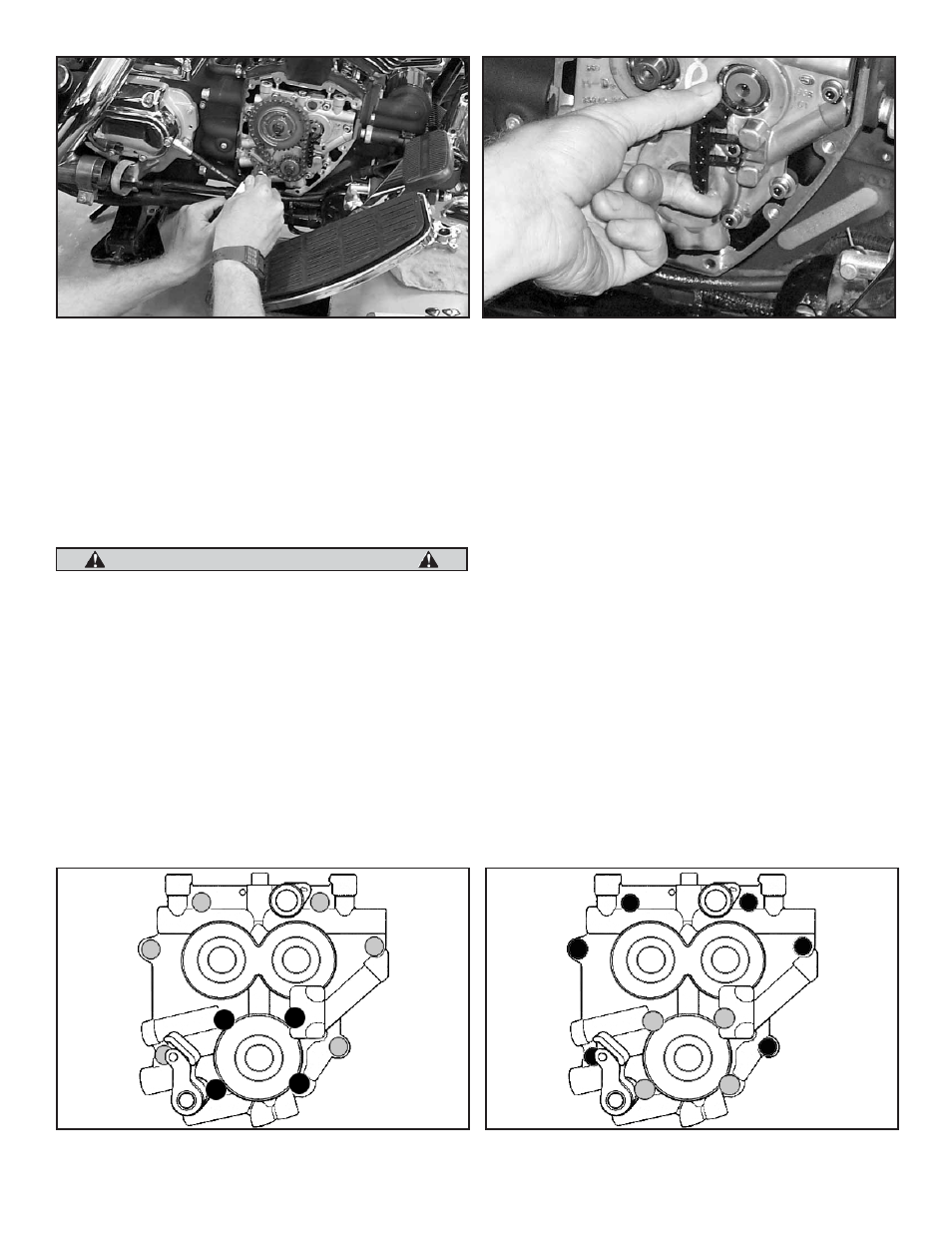
Picture 5
CAUTION
Picture 6
1
1
4
2
2
3
3
6
5
4
Figure 1
Figure 2