Warning caution – S&S Cycle High Performance Valve Spring Kits 90-2079, 90-2080 and 90-2081 User Manual
Page 3
NOTES
●
Installed height is same as outer valve spring length
when valve, spring, and related parts are installed and
valve is in closed position. Correct spring heights are
noted in table.
●
Experienced engine builders may elect to shim valve spring
assembly to installed height less than recommended height
for racing and other special applications. In such cases,
installed height must equal at least Coil Bind Ht. + valve lift
+ .060”. For example, installed height of .660-lift spring kit
90-2079 to be used with .650-lift cam must be at least 1.130”
+ .650 + .060, or 1.840”. Engine-builder bears all
responsibility for utilizing spring height other than those
specified by S&S
®
Cycle.
●
Titanium top collars supplied with Kits 90-2079, 90-2080 and
90-2081 do not require steel wear plate used with some
earlier S&S titanium collars.
●
Installing springs at height less than recommended
dimension will cause rapid spring fatigue. In such cases,
engine should be frequently disassembled for measurement
of spring tension. Decrease in spring tension can cause
extensive engine damage not covered under warranty.
●
Installing springs at height greater than recommended
dimension will decrease spring tension possibly resulting in
valve float and extensive engine damage.
●
Failure to establish required dimensions and clearances may
cause valve seal failure and other, more extensive engine
damage not covered under warranty.
Valve spring assembly is under considerable tension when
compressed and is potentially harmful. Wear eye protection
and take due caution when working with valve springs,
especially when checking for coil bind and during installation.
After assembly, carefully strike tip of valve stem with plastic
hammer to insure that keepers are seated. Direct spring
assembly away from face and body during this procedure.
5. Observing previous warning, check for coil bind as follows:
A.
Place outer spring in vise or spring checking device and
carefully compress to figure equal to Installed Height
(+.020”) - valve lift - .060”. Spring coils must not
bind/contact each other with spring compressed to
measurement obtained by this formula. For example,
compress .660-lift spring kit 90-2079 to be used with
.650-lift cam to 1.900” (+ .020”) - .650” - .060”, or 1.190”.
If adjacent spring coils contact each other with spring
compressed, a different spring pack or cam with less lift
must be used.
B.
Repeat procedure for middle and inner spring for each
spring assembly.
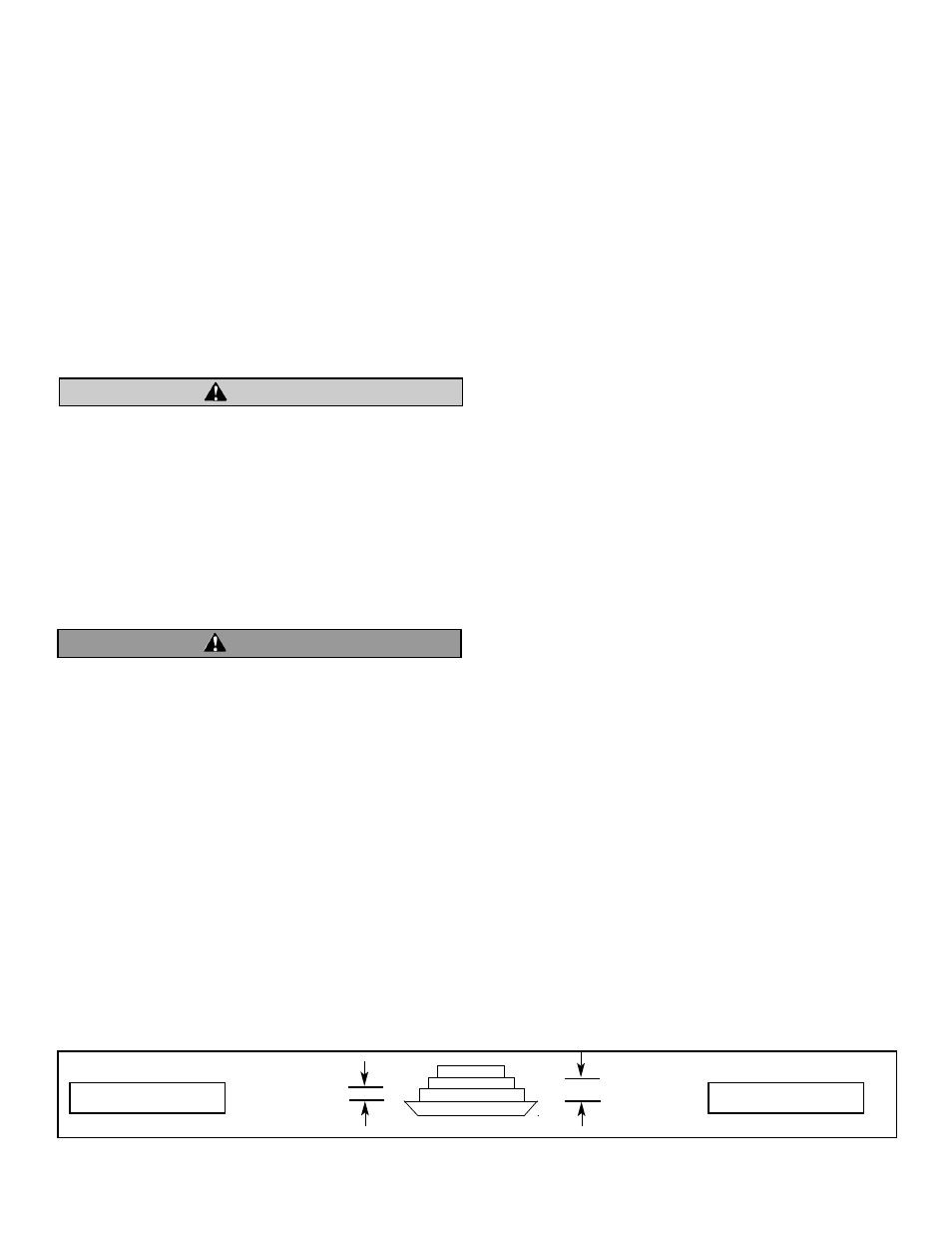
NOTE - Because of steps machined in top collar, middle and inner
springs will have installed heights different than that of outer
spring. To determine correct installed height of middle spring,
subtract Dimension A from installed height of outer spring. See
Figure B, Dimension A. To determine correct installed height of
inner spring, subtract Dimension B from installed height of outer
spring. See Figure B, Dimension B.
6.
Install valves, lower collars, valve seals, and valve
springs in head.
NOTES
●
Springs in Kits 90-2079, 90-2080 and 90-2081 can be installed
with either end up.
●
Installed height should be the same for each spring assembly.
7.
Confirm that rocker arm does not contact top collar. Contact
is most likely to occur when valve is closed. Recommended
clearance is .040”.
8.
Confirm rocker arm to rocker cover clearance.
A.
Install pushrods and rocker assemblies. Adjust pushrods
per manufacturer’s instructions.
B.
Place thin deposit of clay or putty on inside of top rocker
cover directly above pushrod and valve spring areas.
C.
Install top cover and rotate flywheels two complete
revolutions (720˚).
NOTE - If resistance is encountered, remove top cover and
determine cause. Never attempt to force engine past resistance.
D.
Remove top cover and examine clay for possible
indentation caused by rocker arms. Thickness of clay
beneath indentation must be at least .060”. Carefully
remove metal from cover or rocker arm to obtain
required clearance.
NOTE - Remove minimum amount of metal needed to obtain
correct clearance. Care must be taken not to break through
rocker covers or alter rocker arm heat treatment by
overheating while grinding. Oil is supplied to top end through
pushrods and rocker arms, so it also important not to disturb
oil passages in same.
3
WARNING
CAUTION
Dimension A
Dimension B
Figure A