Caution – S&S Cycle High Performance Valve Spring Kits 90-2079, 90-2080 and 90-2081 User Manual
Page 2
S&S
®
valve spring and collar kits 90-2079, 90-2080 and 90-2081 are
designed for street and race applications that utilize camshafts
with extremely high lifts requiring higher than normal spring
pressures. These kits are intended primarily for use on S&S Special
Application heads. .660-lift kit 90-2079 can also be used on S&S
Street Heads normally supplied on S&S engines, or any other
head which can accept a 1.650” outer spring O.D.
NOTE - Kit 90-2079 is a “bolt-in” installation for earlier S&S street
heads equipped with .630” high-lift option that utilizes .085”
longer valves. See following paragraph for part numbers. It
remains the engine builder’s responsibility to confirm all
measurements and clearances during installation.
Kits are designed for “no shoulder” valve guides. Keepers fit
stock
5
⁄
16
” diameter valves and supplied titanium collars or exact
replacement only. In S&S street heads, .660-lift kit requires use of
.085” longer valves 90-2004 (intake) and 90-2005 (exhaust). All
kits are compatible with S&S 90-2013 (intake) and 90-2012
(exhaust) valves supplied with Special Application heads.
Because of special assembly procedures required with high-lift
camshafts and related parts, S&S recommends that these parts be
installed by a professional mechanic having considerable
experience with parts of this nature.
●
Improper assembly including failure to establish proper
measurements and clearances can cause extensive engine
damage which is solely the responsibility of the installer.
●
Mixing valves, springs, collars, keepers or other parts from
different valve spring kits can cause extensive engine
damage which is also the responsibility of the installer.
NOTE - S&S valve spring kits 90-2079, 90-2080 and 90-2081
feature triple valve springs. 90-2079 and 90-2080 utilize flat
middle spring. 90-2081 has round middle spring.
Spring Installation Procedure
1.
If applicable, remove cylinder heads from engine and
disassemble. If cylinder heads/valves are to be reconditioned,
proceed according to standard procedure at this time. Refer
to appropriate service manual or consult professional
mechanic as needed.
2.
Place lower spring collar in valve spring pocket in head.
Place outer spring on collar. Collar must rest flat on head
and spring coils must not contact sides of spring pocket in
head. If necessary, machine lower collar and/or spring
pocket to obtain minimum clearance of .030”. Do not
modify spring in any way.
3.
Using following procedure, determine installed spring
height and clearance between top collar and valve guide.
A.
Lubricate valve stem and install valve in guide.
B.
Install bottom collar, valve guide seal, top collar and
valve keepers. Pull top collar tightly against keepers to
seat keepers in collar.
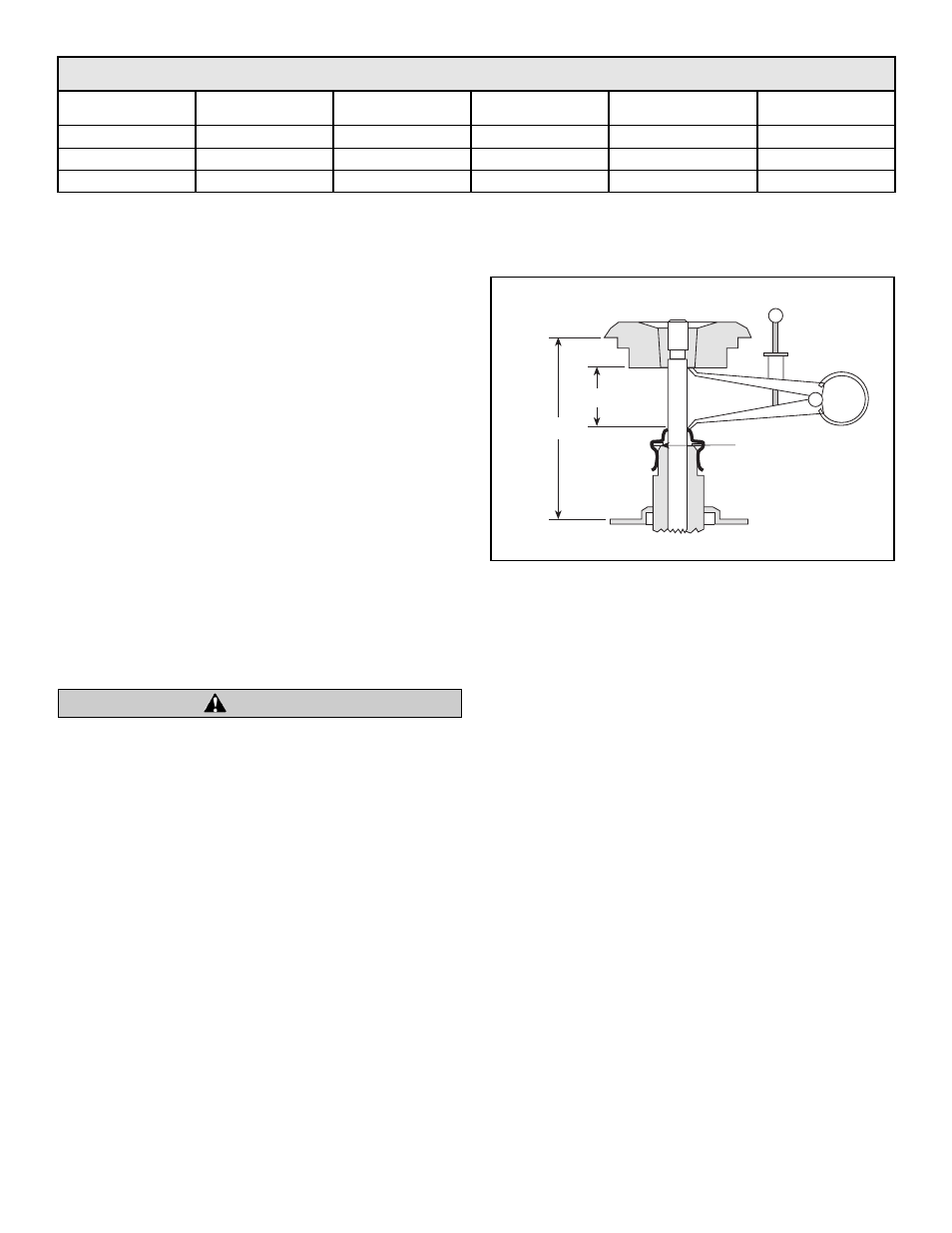
C.
While holding valve firmly against seat in closed
position, measure installed spring height (distance
between lower valve spring seating surface and outside
step of top collar). See Figure A, Dimension A. Record
measurement.
D.
Measure distance between top collar keepers and top of
valve guide or seal (if applicable). See Figure A,
Dimension B. Distance must be at least .060” greater
than valve lift of cam to be used. If distance is less, valve
guide must be shortened to obtain required clearance.
E.
Repeat Steps A-D for remaining valves and record all
measurements. Label and keep track of all parts during
assembly to insure they are installed in same location
and with same valves that measurements were
obtained with.
4.
Adjust installed spring heights to dimension shown in
specifications table above. If installed height is too high,
place shims under lower collar to achieve correct height.
Shims are available from S&S and local sources such as
automotive parts houses. If spring height is too low, grind
valve or valve seat or machine spring floor in cylinder head
to achieve correct height.
2
SPECIFICATIONS
Part Number
Maximum Lift
Installed Height
Seat Force
Force @ Maximum Lift
Coil Bind Height
90-2079
.660”
1.900”
210 lbs.
520 lbs.
1.130”
90-2080
.720”
1.975”
250 lbs.
625 lbs.
1.175”
90-2081
.800”
2.000”
285 lbs.
790 lbs.
1.140”
CAUTION
Remove seal and grind
guide here to obtain
greater measurement B.
B
A
Figure A
Dimension A: Installed spring height must be
adjusted to above specification + /- .020”
Dimension B: Must be .060” greater than valve lift for camshaft to be used.
Remove seal and grind
guide here to increase
dimension B.