S&S Cycle Cams for Panhead, Shovelhead, & Harley-Davidson Evolution Engines User Manual
Page 6
6
7
2. Hydraulic lifters.
a. Turn adjusting screw until pushrod contacts lifter and all free play is removed.
b. Turn adjusting screw an additional 4 to 41⁄2 turns (24-27 flats), and tighten locknut. Allow sufficient time for lifter to bleed down.
Pushrod will spin freely after lifter bleeds down. It is imperative that engine not be rotated until lifter spins freely.
c. Rotate engine to place next pushrod at lowest point on cam and repeat procedure. Repeat for remaining pushrods.
3. Harley-Davidson® Evolution® hydraulic lifters with S&S® HL
2
T Limited Travel Kit. (Adjustable pushrods must be used with HL
2
T Kit.)
a. Lengthen pushrod adjuster 20 flats to fully collapse lifter. Pushrod will be extremely difficult to turn by hand.
NOTE: It may take as long as twenty minutes for lifter to fully collapse. Wait 20 minutes and attempt to rotate pushrod by hand. If pushrod cannot be
rotated with moderate effort, proceed to Step B. If pushrod can be rotated, extend adjuster 10 additional flats, wait 20 minutes and attempt to rotate
pushrod again. Do not proceed until pushrod cannot be rotated after 20 minutes.
b. After lifter is fully collapsed, shorten adjuster exactly to point where pushrod can be rolled between thumb and forefinger with
minimum effort.
NOTE: Some lifters with HL
2
T Kit provide quieter operation if pushrod adjuster is shortened 3 to 6 additional flats from point where pushrod can just be
turned by hand. The additional travel that results may improve the ability of the hydraulic unit to fill with oil and operate at zero lash.
c. Tighten locking nut against pushrod and confirm that pushrod adjustment remains correct.
d. Rotate engine to place next pushrod at lowest point on cam and repeat procedure. Repeat for remaining pushrods.
NOTE: If hydraulic units contain oil allow sufficient time for lifter to bleed down before final adjustment is made.
Do not turn engine until lifter is fully bled down and adjustment has been made. Valves could contact each other and cause damage.
9. Valve Spring Installation Information
A. Installation of an S&S® high lift racing valve spring kit may require that the spring pocket of the head be machined to the proper diameter.
Lower valve spring collar should seat completely flat on cylinder head surface and lower coils of valve spring should not touch sides of
spring pocket.
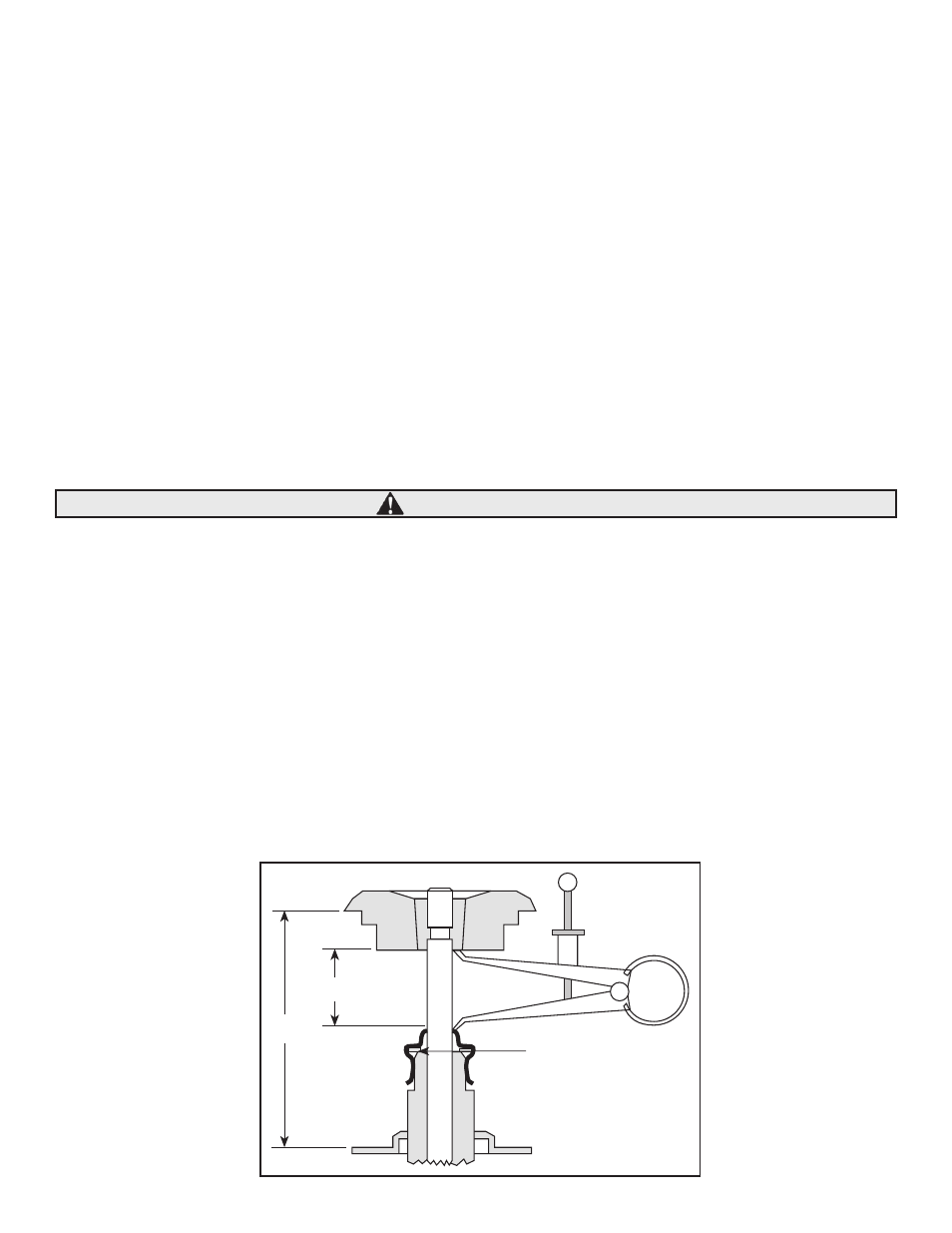
B. Heads must be removed to check the installed spring height. This is the distance from the bottom of the top retainer to the top surface
of the lower valve spring collar where the spring rests on the head (Dimension A, Figure 1). This distance is the height of the outer valve
spring when the valve is on the seat (typically 1.490" to 1.520" for panheads and shovelheads and 1.800" for Evolutions). Install the valve in
the guide. Then install the bottom collar, top retainer and keepers. Pull the top retainer tightly against the keepers. While holding the valve
assembly steady, measure the distance between the lower valve spring seating surface and the outside step of the top retainer. Record your
information.
After you have measured all the valves, find the shortest height. This will become the installed height for all the valve springs.
C. Once you have determined the installed height, use shims to obtain the same installed height for all valve springs (+.020" is acceptable).
Extra shims are available through S&S, if needed.
D. Before removing the retainers, measure the distance from the bottom of the retainer to the top of the valve guide or valve seal. (Dimension
B, Figure 1). This distance must be .060" greater than the lift of the valve. If not, the guide must be shortened to obtain clearance. Insufficient
clearance between top collar and valve seal is a very common cause of early camshaft fatigue and valve seal failure.
CAUTION
Remove seal and grind
guide here to obtain
greater measurement B.
B
A