S&S Cycle Cams for Panhead, Shovelhead, & Harley-Davidson Evolution Engines User Manual
Page 5
4
5
Failure to follow instructions and perform any required clearancing procedures may result in insufficient clearances between valve train
parts and other engine components causing damage to engine.
6. Other Information
A. All S&S cams are ground to fit needle roller style crankcase cam bearings. If an S&S cam is installed in an early set of big twin crankcases with
a bushing style cam bearing, then the bushing must be reamed to fit the bearing diameter of the camshaft.
B. In all 1948 to early 1984 installations where solid lifter style tappets are used S&S recommends plugging the hydraulic lifter oil feed holes
in the tappet blocks. If this procedure is not performed, excessive oil can bleed off the cam followers and fill the pushrod tubes causing
leakage. To perform this modification thread an 8-32 tap into the oil passage hole in the gasket surface and turn the tap until it just starts to
enter the cam follower hole. Then, screw an 8-32 x 3⁄16" allen head set screw in place to block the hole.
NOTE: If hydraulic lifters are ever reinstalled, these screw plugs must be removed.
7. Cam Gear Measuring
A. Start by installing .105" pins 180° apart on the cam gear—a rubberband will help hold them in one place.
B. Use a micrometer to measure the assembly and make a note of the dimension. Transfer the pins to the pinion gear and measure it also.
C. Match the pinion gear to the size closest to it in the chart below. The closer the sizing the less noise you will encounter.
D. Install the pinion and cam dry, use a new gasket and torque the cam cover in place. Verify in four different spots that the cam slides easily
and consistently across the pinion gear and check backlash at the same time.
E. Once you have verified that the fit is proper lubricate everything and move on to final assembly.
8. Camshaft Installation Procedure
A. Remove pushrods. Pushrods can be removed from panheads and shovelheads by setting adjusters to shortest adjustment. It is necessary to
remove the rocker cover and rocker arm for pushrod removal and installation in a Evolution® engine.
B. Remove stock camshaft. Measure length of stock camshaft and new camshaft. If lengths are not equal (should be close to 3.025") change
spacer shims to make up any difference. Shovelhead and Evolution® engines use same shims. Camshafts for 1988 and later Evolution®
engines need to be shimmed to 3.075" (+.050" longer) because of a factory design change. Many engine builders replace inner camshaft
bearing when installing cam. Refer to Harley-Davidson® service manual for correct procedure.
NOTE: S&S recommends that when installing high performance cams in 1992 and later big twin engines, the inner camshaft bearing (marked INA SCE 138
USA), should be replaced with a Torrington B138 bearing (AP part #292310, S&S part 31-4009). The Torrington bearing has a higher radial load rating and is
better able to handle increased stress of high performance cams.
Use of the stock 1992 and later inner camshaft bearing with high performance camshaft may result in bearing failure, and cause serious
engine damage.
C. Install new cam and check for proper endplay. Endplay for installed camshafts should be .005" to .015".
D. Install lifters and pushrods. The longest pushrod is for front exhaust, next longest pushrod is for rear exhaust, and two shortest pushrods are
for front and rear intakes.
E. Adjust pushrods - In all cases engine must be cold and lifter to be adjusted must be at lowest position for pushrod adjustment.
1. Solid lifters. (All Engines)
a. Turn adjusting screw until free play is removed, and pushrod can be turned between thumb and forefinger with some drag.
b. Tighten locking nut, and recheck pushrod adjustment to insure that adjustment is still correct.
c. Rotate engine to place next pushrod at lowest point on cam and repeat procedure. Repeat for remaining pushrods.
CAUTION
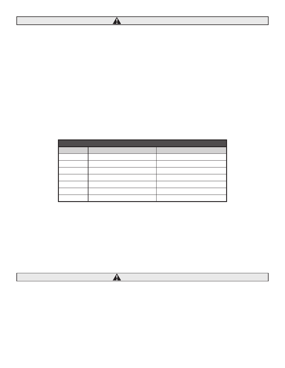
GEAR DIAMETER CHART
Color
Pinion Gear Diameter over .105" Pins
Cam Gear Diameter Over .105" Pins
Orange
1.4751-1.4756
2.7324-2.7334
White
1.4745-1.4751
2.7334-2.7344
Yellow
1.4737-1.4745
2.7344-2.7354
Red
1.4729-1.4737
2.7354-2.7364
Blue
1.4721-1.4729
2.7364-2.7374
Green
1.4715-1.4721
2.7374-2.7384
Black
1.4710-1.4715
2.7384-2.7394
CAUTION