Bunn C User Manual
Page 23
Page 23
RECOVERY BOOSTER RELAY (OPTIONAL)
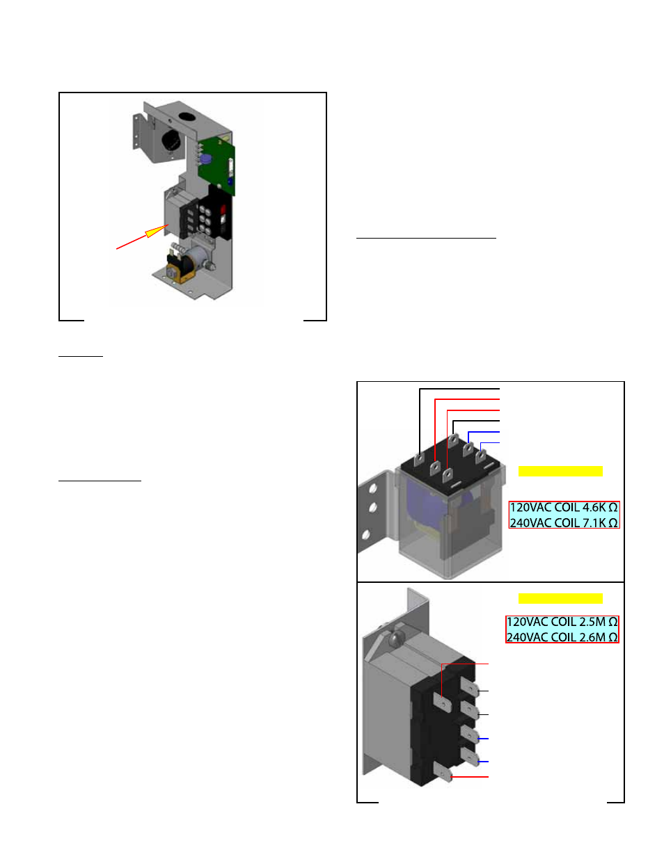
FIG. 23-1 RECOVERY BOOSTER RELAY
Location
The recovery booster(s) are located inside the trunk
on the center of the component brackets just above
the solenoid valve. The coil is activated by the timer/
solenoid circuit. The contacts then close, bypassing
the mechanical thermostat, thereby allowing faster
heating of the incoming water in the tank.
Test Procedures
1. Disconnect the brewer from the power source.
2. Disconnect the white and black wires from the coil
of the recovery booster relay.
3. With a voltmeter, check the voltage across the
white and the black wires. Connect the brewer
to the power source and initate a brew cycle. The
indication must be 120 volts ac.
4. Disconnect the brewer from the power source.
If voltage is present as described, proceed to #5.
If voltage is not present as described, refer to Wiring
Diagrams and check the brewer wiring harness.
5. Check the resistance across the coil's terminals.
If resistance is present as described in FIG 9, reconnect
the white and black wires to the coil.
If resistance is not present as described, replace the
relay.
6. Disconnect the blue and black wires from the relay
contact terminals. Connect the brewer to the power
source. With the "ON/OFF" switch in the "ON" po-
sition and the start switch pressed and released,
check for continuity across relay terminals.
7. Disconnect the brewer from the power source.
If continuity is present as described, reconnect the blue
and black wires to the relay contact terminals.
If continuity is not present as described replace the
relay.
Removal and Replacement:
1. Remove all wires from the relay.
2. Remove the two #8-32 screws securing the relay
mounting bracket to the component bracket. Re-
move relay bracket and relay as an assembly.
3. Remove the screw securing the relay to the relay
mounting bracket.
4. Install new relay to the component bracket.
5. Refer to Fig. 9 when reconnecting the wires.
EARLY MODELS
1 = COIL to TIMER
LATER MODELS
4-7 = N.O. to THERMOSTAT
6-9 = N.O. spare
A = COIL to TIMER
B = COIL to TIMER
A
4
7
B
6
9
6-8 = N.O. not used
2-4 = N.O. to THERMOSTAT
0 = COIL to TIMER
FIG. 23-2 BOOSTER RELAY TERMINALS
8
6
4
2
1
0
41711.1 052009