S&S Cycle Billet Rocker Cover Assemblies for Harley-Davidson evolution engines User Manual
Page 6
and without resistance. If resistance is encountered, loosen screws and shift supports to align dowels with openings.
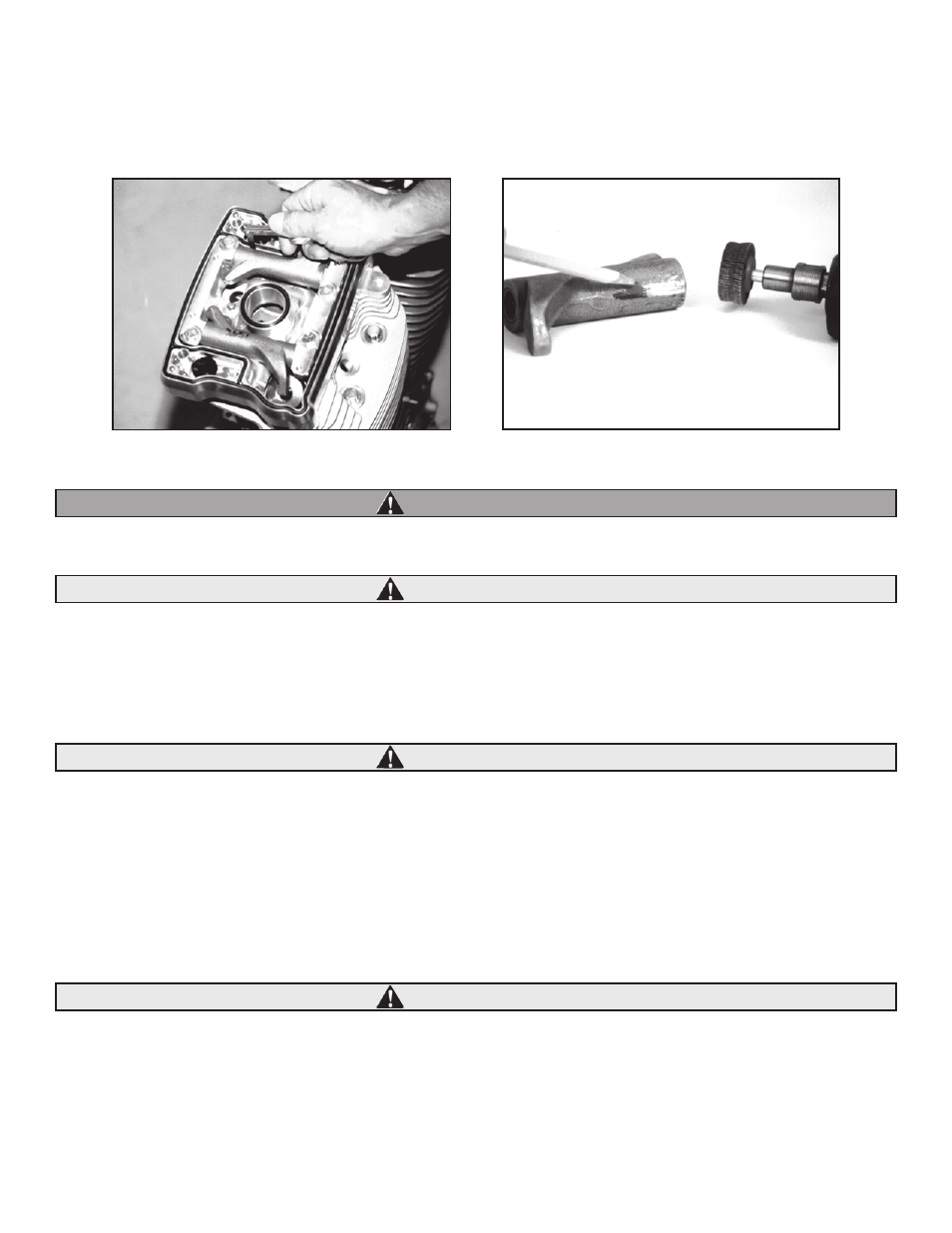
B. Measure space between rocker arm and rocker cover with feeler gauge. See Picture 6. Minimum acceptable clearance is .025".
C. If clearance is less than .025", remove rocker arm from cover and carefully file or grind rocker arm to obtain correct clearance. See Picture 7.
Metal particles are potentially hazardous, especially to hands and eyes. Always wear protective clothing such as goggles and gloves when
grinding or filing metal. When using compressed air, always direct air stream away from yourself and others nearby.
S&S recommends clearancing rocker arm rather than rocker cover. However, removing excessive material may weaken rocker arm resulting
in engine damage. In most instances, only a few thousandths of an inch of metal must be removed for correct clearance. Also, grind work
piece for only brief periods to avoid overheating and possible alteration of heat treatment.
D. Remove burrs and smooth rough areas of relieved area with fine file or polishing wheel on hand held grinder. Clean rocker arm thoroughly
with solvent and compressed air observing warning above.
Failure to remove burrs and metal chips may result in engine damage not covered under warranty.
E. Reinstall rocker arm and confirm correct clearance.
10. Check rocker arm endplay by sliding rocker arm as far to one side as possible and measuring gap between rocker arm and rocker arm support
on opposite end. Acceptable endplay is .001-.012". If endplay is insufficient, carefully remove material from end of rocker shaft to achieve correct
endplay, leaving smooth, nonabrasive surface.
NOTE: If endplay is insufficient, remove minimum amount of material required to achieve correct measurement.
Failure to establish correct end play can result in engine damage not covered under warranty.
11. Remove rocker/support assembly and replace pushrods, insuring correct locations according to pushrod length. Lubricate valve tips and
contact areas of rocker arms and reinstall rocker/support assembly as in previous step. Contact areas include roller, pushrod socket, and end
thrust surfaces.
6
7
Picture 6
Picture 7
WARNING
CAUTION
CAUTION
CAUTION