S&S Cycle Billet Rocker Cover Assemblies for Harley-Davidson evolution engines User Manual
Page 5
Improperly tightened fasteners may cause damage not covered under warranty.
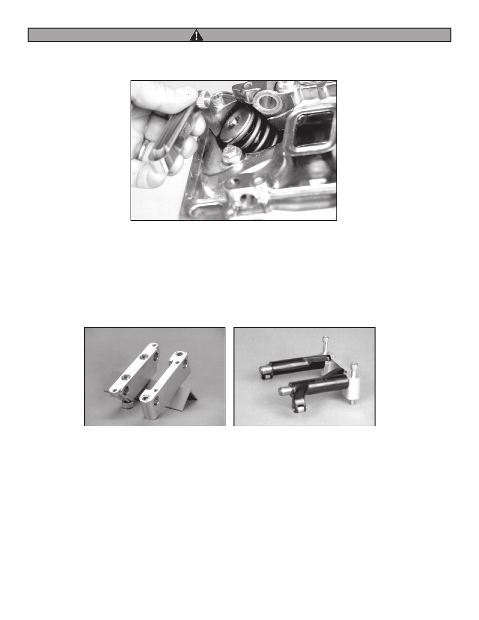
7. Measure clearance between valve spring and rocker cover with feeler gauge. Minimum is .060". See Picture 3. Same clearance must exist
between rocker arm and top cover.
NOTE: If less than .060" clearance exists between rocker and top cover, contact S&S Technical Services Dept.
8. Assemble right and left rocker shaft supports. Inspect rocker shafts for burrs and deburr as necessary. Lubricate shaft for exhaust side rocker arm
with assembly lube and pass through forward opening in right support. Relief in shaft must align with bolt hole indicated by arrow in Picture
4. Also note that relief in shaft support must face center of engine. Install flat washer on 5⁄16" x 21⁄2" capscrew, pass screw through opening in
support and apply Loctite® 242 or equivalent to threads. Lubricate rocker arm bushings and shaft and place exhaust side rocker arm on shaft.
Repeat for intake and install second 5⁄16" x 21⁄2" capscrew in support. See Picture 5.
NOTE: S&S® has experienced minor clearance problems when installing some Harley-Davidson® rocker arms in S&S billet rocker covers. Procedure described
in Step 9 should be performed prior to pushrod installation.
9. To confirm adequate clearance between rocker arm and cover:
A. Place rocker/support assembly in rocker cover base. Place left side support over ends of shafts and install 5⁄16" x 21⁄4" capscrews in support.
Evenly tighten 4 capscrews in X-pattern to 15-18 ft-lbs. Slowly rotate rockers back and forth to insure that movement is free and without
bind.
NOTES:
• Most Softail® frames require that right support be placed in lower rocker housing with rockers attached, then tilted up for installation of left support. In
some applications, notably those with rubber mount engines and/or custom frames, both rocker supports can be installed on shafts and assembly placed
in rocker housing base as single unit.
• Rocker arm supports have locating dowels in bottom surface. Dowels must align with openings in rocker housing base. Supports must pull down evenly
4
5
Picture 3
Picture 4
Picture 5
WARNING