Installation bracket – RKI Instruments GD-K7D2 (115 VAC) User Manual
Page 9
Model GD-K7D2 (115 VAC) Sample Draw Transmitter • 5
output during start-up and calibration procedures.
Gain pot
The gain pot is below the zero pot. It is used to make coarse span adjustments. The gain
pot is factory set and for adjustment by a field service technician only
.
Another factory adjust pot is located below the gain pot. Do not adjust this pot.
Output check pins
Two output check pins [marked 1 (+) and 2 (-)] are below the pots. Use the output check
pins to read the signal output of the GD-K7D2 with a milliampmeter during the start-up
and calibration procedures.
Pump
The pump is behind the sensor. The pump pulls the test sample into the GD-K7D2. The
pump operates on 115 VAC.
Lithium Battery Pack
A 3.6 volt lithium battery pack is above the pump on the right side of the GD-K7D2. The
lithium battery pack maintains a bias voltage on the gas sensor when the GD-K7D2 is not
receiving incoming power, such as during shipment or storage. If the GD-K7D2 is off
power for an extended period and the lithium battery pack is dead, the gas sensor
operation will be affected when the GD-K7D2 is started up. See Storing the GD-K7D2 in
the Maintenance section for battery pack replacement recommendations.
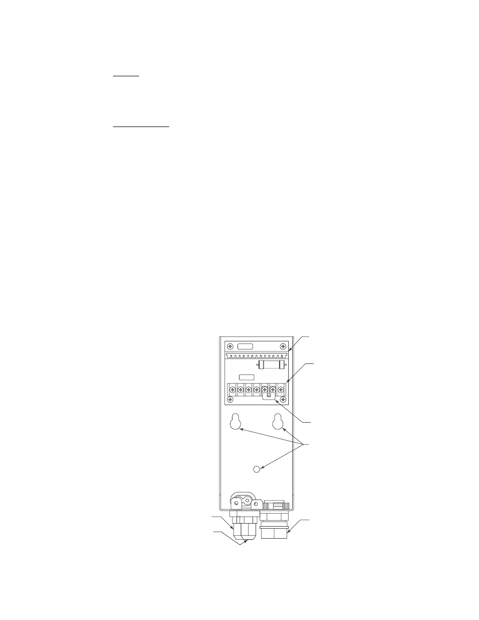
Installation Bracket
The L-shaped installation bracket facilitates mounting and wiring of the GD-K7D2. The
three mounting holes on the back of the bracket are used to mount it to a vertical surface.
The installation bracket includes the socket, external wiring terminal strip, cable bushing,
and sample fittings.
Figure 4: Installation Bracket Component Location
Socket for
Main Board
External Wiring
Terminal Strip
Mounting Holes
Cable Bushing
Gas In
Sample Fitting
Gas Out
SampleFitting
Factory Installed
Jumper
*
*
Jumper is factory installed when
GD-K7D2 is used with a controller
that does not have a built in flow
alarm circuit and flow alarm
wiring terminals.