RKI Instruments Eclipse User Manual
Page 8
8
Eclipse Detector Head Operator’s Manual
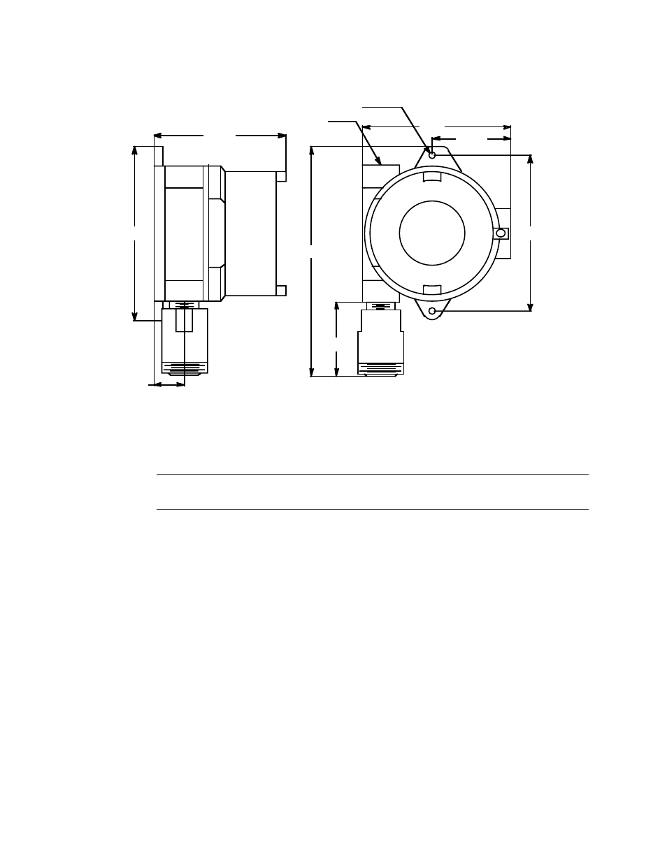
Figure 4: Outline & Mounting Dimensions, Oxygen
Wiring the Eclipse
WARNING: Always verify that the power source is off or disconnected before
performing any wiring.
1.
Remove the junction box cover.
2.
Grasp the round Eclipse nameplate though which the LCD display is visible.
3.
Gently pull until the control PCB is pulled away from the junction box. The detector
and power/signal terminal strips are now visible on the interconnect PCB. Take care
not to pull too hard and damage the cable which connects the top and bottom PCB’s.
4.
If necessary, disconnect the cable from the interconnect PCB and lay it aside with the
control PCB.
5.
Verify that the detector leads are wired to the detector terminal strip as shown on the
wiring label which is on the bottom PCB:
•
Combustible gas detector.
Red wire to terminal labelled LEL RED, white wire to terminal labelled LEL WHT,
green wire to terminal labelled LEL GRN, black wire to terminal labelled LEL
BLK.
3/4 CONDUIT ENTRY
Ø .25 MOUNTING HOLES (2X)
4.60
1.1
5.46
2.75
5.2
8.0 max
6.1
2.6 max