Start up, Introducing incoming power – RKI Instruments 65-2615RK-05-04 User Manual
Page 20
15
65-2615RK-05-04 M2 Transmitter Operator’s Manual
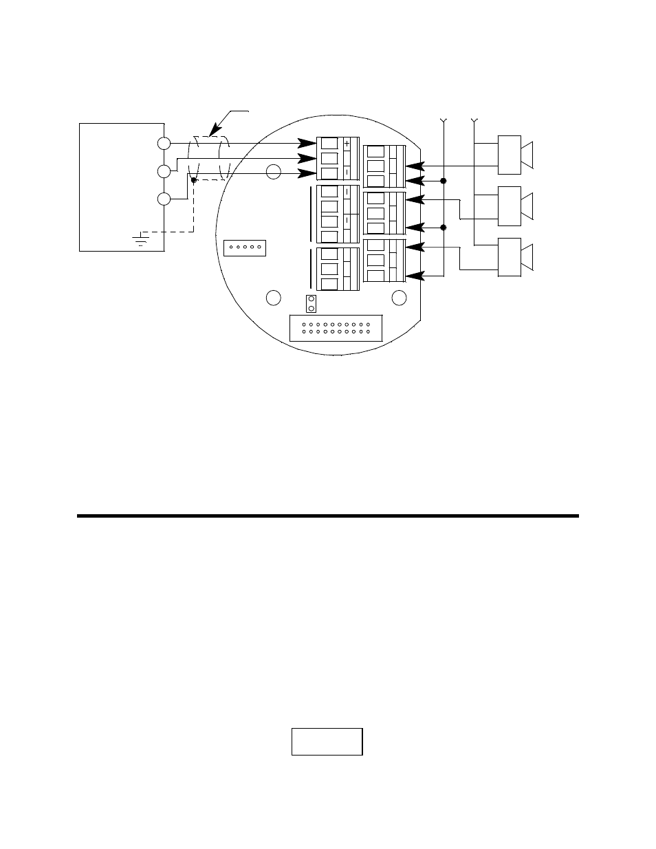
See Figure 7 below for field wiring connections to the M2.
Figure 7: Wiring the M2 Junction Box to a Controller and Alarm Devices
16. Re-install the control PCB (and ribbon cable if necessary). Be sure the ribbon cable is
routed down below the control PCB so it will not be damaged by the cover when it is
screwed back on.
17. Secure the M2 junction box cover to the junction box.
18. Make controller, device, and relay connections as appropriate. If shielded cable is
used for the PWR/SIG connections, connect the cable shield’s drain wire to an
available chassis ground at the gas monitoring controller, recording device, or
programmable controller.
Start Up
Introducing Incoming Power
1.
Complete the installation procedures described earlier in this manual.
2.
Verify that all wiring connections are correct and secure.
3.
Turn on the incoming power.
4.
If necessary, turn on the controller or other monitoring device that is connected to the
M2.
5.
The LCD display will indicate the firmware version when the M2 is first powered up
and will then count down a one minute warm-up period before normal operation
begins. During normal operation, the display will indicate the target gas and current
gas reading. Verify that the display is indicating the target gas and current gas reading
after the warm-up period is complete and normal operation begins.
Alarm Device
Power
Alarm 1
Alarm
Device
Fail
Alarm
Device
+
S
PW
R
/SI
G
C
NC
NO
FA
IL
Alarm 2
Alarm
Device
Typical Alarm
Wiring Shown
AL
AR
M
2
A
B
C
RS
4
8
5
RKI Controller
Terminals
(24 VDC) -
4 - 20 mA In (S)
(24 VDC) +
C
NC
NO
C
NC
NO
AL
AR
M
1
See
Detector
Wiring
See
Modbus
Wiring
Cable Shield
+
TOX
IC
O
X
Y
H2S
0 ppm