Chapter 2: description, Overview, External description – RKI Instruments M2 for 12 VDC User Manual
Page 8
3
M2 Transmitter Operator’s Manual, 12 V DC Operation
Chapter 2: Description
Overview
This chapter describes external and internal components of the M2 Transmitter.
External Description
This section describes the junction box and all external components of the M2 transmitter.
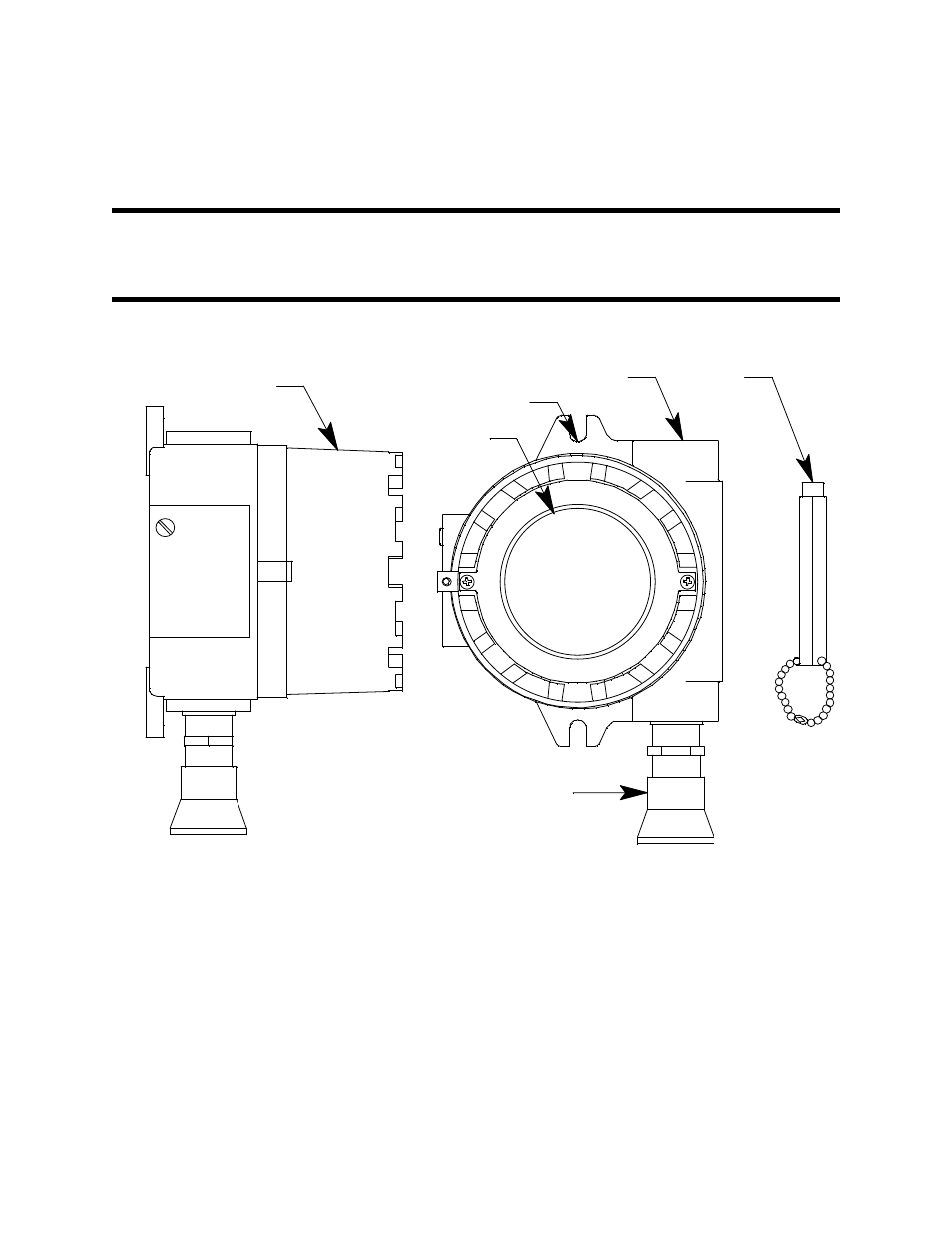
Figure 1: M2 External Components
Junction Box
The M2’s cast aluminum junction box is dust and weather resistant. The junction box also
protects the M2 and all connections made to it. Use the two 3/4 in. conduit hubs to mount
the detector to the junction box (factory installed in the bottom hub) and connect wiring
from an external device (top hub).
Use the junction box’s two mounting holes to mount the M2 to a vertical surface at the
monitoring site. The window in the cover on the front of the junction box allows you to
view the LCD display and use the magnetic wand to actuate the magnetic control
switches so you can perform non-intrusive calibration. Removing the cover allows you to
access the interior of the junction box.
Magnetic
Wand
3/4 NPT Conduit Hub
Junction Box Cover
Mounting Slot (2x)
Window
Detector
(Catalytic LEL Detector Shown)