RKI Instruments M2 for 12 VDC User Manual
Page 15
M2 Transmitter Operator’s Manual, 12 VDC Operation
10
be used, use a two or three conductor shielded cable or two or three wires in
conduit for connections to the power/signal terminal strip depending on whether
or not the signal (S) terminal is used.
•
If the PWR/SIG connections and one or more relays are used, route the
connections to the M2 in conduit. Use shielded cable in the conduit for the PWR/
SIG connections and unshielded cable or individual wires for the relay
connections. Make sure any wire or cable used for relay wiring is appropriately
rated for the power that it will carry.
NOTE:
If shielded cable is used for the PWR/SIG connections, leave the cable shield’s
drain wire insulated and disconnected at the M2. You will connect the opposite
end of the cable’s drain wire at the controller or device.
•
If the M2 will be wired into a Modbus network, see “Chapter 8: RS-485 Modbus
Output” on page 29.
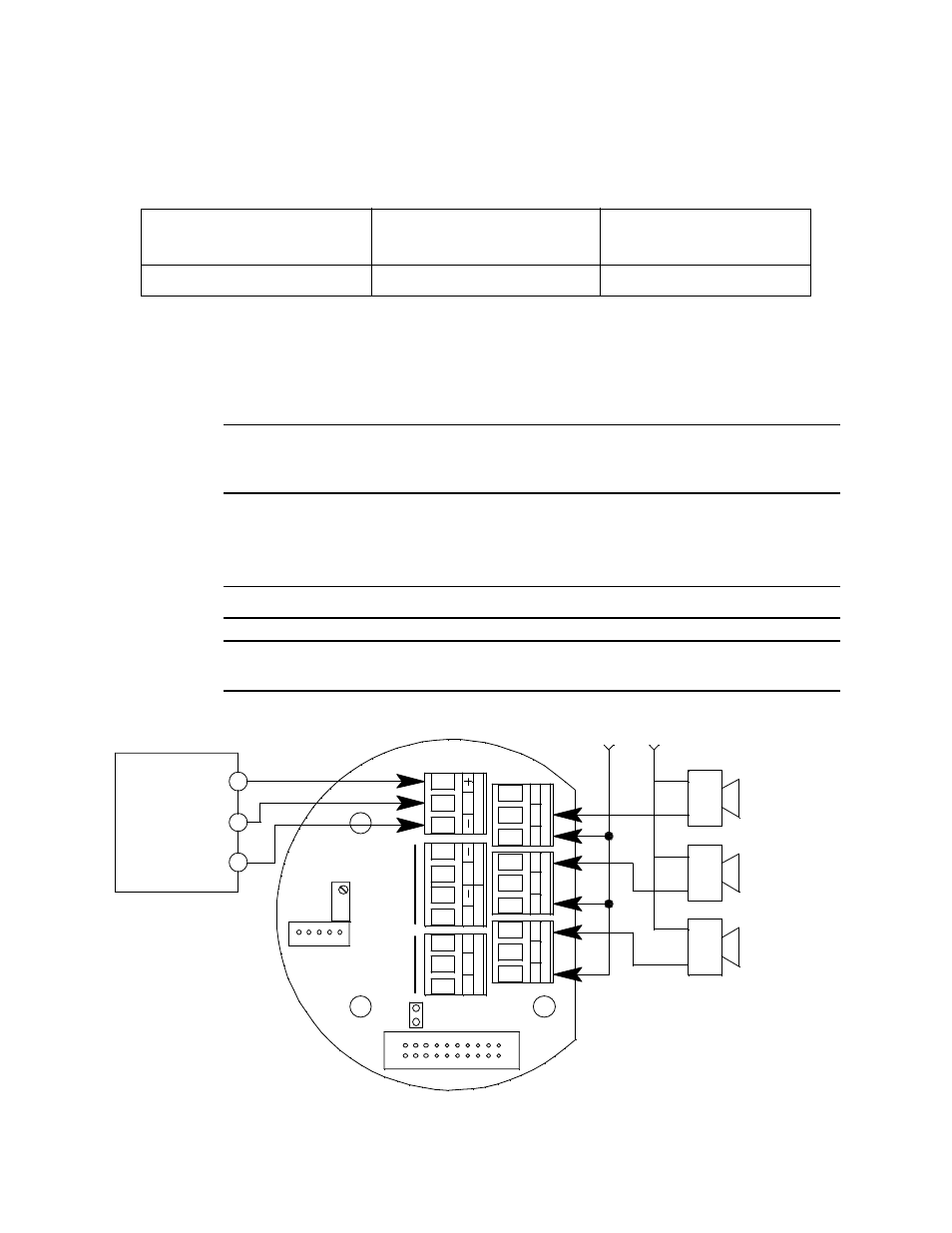
See Figure 5 below for field wiring connections to the M2.
CAUTION:
Do not connect 24 VDC power to a 12 VDC M2.
WARNING:
If the M2 is installed in a hazardous location, use appropriately rated
conduit, conduit fittings, and construction technique.
Figure 5: Wiring the M2 to a Controller and Alarm Devices
Table 3: Wire Size for PWR/SIG Connections
Max Distance to Controller w/
18 Gauge Wire
Max Distance to Controller
w/16 Gauge Wire
Max Distance to Controller
w/14 Gauge Wire
2,500 ft.
5,000 ft.
8,000 ft.
S
PW
R
/SI
G
+
C
NC
NO
FA
IL
Alarm 1
Alarm Device
Fail Alarm
Device
Alarm Device
Power
A
B
C
RS
48
5
AL
AR
M
2
(24 VDC) -
4 - 20 mA In (S)
(24 VDC) +
RKI Controller
Terminals
Typical Alarm
Wiring Shown
Alarm 2
Alarm Device
+
See
Modbus
Wiring
C
NC
NO
TO
X
IC
O
X
Y
C
NC
NO
AL
AR
M
1
See
Detector
Wiring