Description, Detectors – RKI Instruments 65-2485RK-02 User Manual
Page 6
2 • 65-2485RK-02 Multi Point Detector
Description
This section describes the multi-point detector. It consists of the detectors, the terminal
strips, the conduit seal, and the junction boxes.
Detectors
This section describes the components of the various detectors that are used with the
65-2485RK-02.
Oxygen Detector
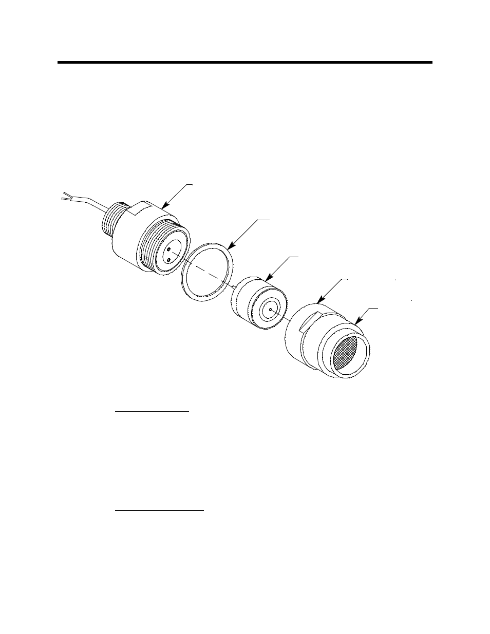
The detector consists of the oxygen sensor, the detector housing body, detector housing
cap, and cap gasket.
Figure 1: Oxygen Detector Component Location
Detector Housing Body
The detector housing body protects the electronic components within the housing. Use the
mounting threads at the top of the housing to screw the oxygen detector into the 3/4”
NPT hub on the bottom of the junction box. Two wires extend from the top of the detector
housing body. Use these wires to connect the oxygen detector to the terminal block. One of
the wires is white and one of the wires is green.
The housing includes two sockets installed on a circuit board. These sockets accept the
plug-in sensor’s two pins to provide electrical connection for the sensor. The circuit board
with the sockets conditions the sensor’s signal before the signal reaches the controller.
Housing Cap & Cap Gasket
The housing cap screws onto the detector housing. It retains the plug-in sensor and
protects it from damage. A foam gasket is installed inside the housing cap that seals
against the sensor face. The housing cap also includes a flame arrestor which contains any
sparks that may occur within the detector and a flame arrestor guard which protects the
flame arrestor from damage. Unscrew the detector cap to access the plug-in sensor for
maintenance or replacement. A cap gasket seals the interface between the housing and
Detector Housing Body
Detector Housing Cap
Flame Arrestor
Guard
Plug-in Oxygen Sensor
Cap Gasket