Description, Combustible gas detector – RKI Instruments 65-2405RKSS User Manual
Page 6
2 • 65-2405RKSS Combustible Gas Transmitter
Description
This section describes the components of the combustible gas transmitter. The transmitter
is a 4 - 20 mA type detector head. It consists of the combustible gas detector, amplifier, and
junction box.
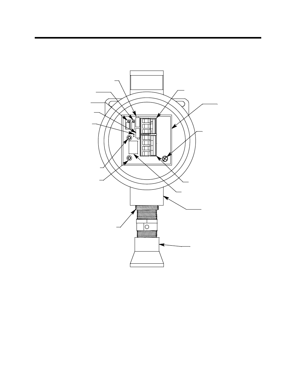
Figure 1: Combustible Gas Transmitter Component Location
Combustible Gas Detector
The combustible gas detector is a catalytic type detector that produces an electrical output
that corresponds to the detection range. It is packaged in a 1/2 inch NPT nipple with a
sintered metal flame arrestor on one end allowing ambient air to diffuse into the detector.
The flame arrestor also contains any sparks which may occur within the detector. The 1/2
inch NPT mounting threads at the top of the detector allow you to mount it into the
bottom conduit hub of the junction box. A 3/4 in. x 1/2 in. NPT reducer is necessary to
install the combustible gas detector in the junction box. A rainshield screws onto the
bottom of the detector (flame arrestor end). The rainshield helps protect the detector from
rain and debris in the monitoring environment. Four color-coded leads extend from the
top of the detector. The leads allow you to connect the detector to the amplifier.
G
PW
R
/
S
IG
LE
L
W
RB
Mounting Screw
Amplifier
Zero Pot
LEL Detector
Detector Term inal Strip
J-Box
Detector (sensor) Current
Label
Controller Terminal Strip
Factory Adjust Pot
Jumper Pins,
Factory Use Only
ZE
R
O
SP
A
N
Red + Test Point
Black - Test Point
Reducing Bushing,
3/4 NPT to 1/2 NPT
Factory Adjust Pot
Span Pot
S
e
ns
or
C
ur
rent
1
48mA
S