Description, Combustible gas detector – RKI Instruments 65-2400RK-05 User Manual
Page 2
Combustilbe Gas Transmitter • 2
Description
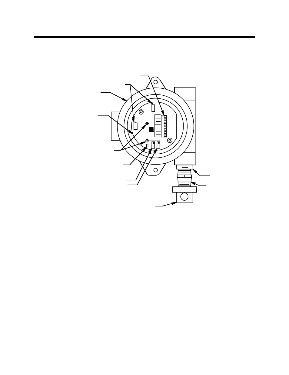
This section describes the components of the combustible gas transmitter. The transmitter
consists of the combustible gas detector, amplifier, and junction box.
Figure 1: Combustible Gas Transmitter Component Location
Combustible Gas Detector
The combustible gas detector includes the sensing elements, flame arrestor, flame arrestor
guard, detector housing, and detector leads.
Sensing elements
Two sensing elements are protected within the detector assembly. Through a series of
thermal and electronic reactions, these elements produce an electrical output that is
proportional to the detection range of the transmitter.
Flame arrestor
The porous flame arrestor allows the target gas to diffuse into the detector assembly and
contact the sensing elements. The flame arrestor also contains sparks within the detector.
Flame arrestor guard
The flame arrestor guard is permanently bonded to the detector housing and protects the
flame arrestor from impact damage.
C OMBUSTIBLE
D ETECTOR
3/4" X 1/2"
REDUCER
AMPLIFIER
J-BOX
FACTORY SET POTS
FLAME ARRESTOR GUARD
IN TERCON NECT TERMINAL STRIP
TP
+
TP
ZERO
SPAN
GND
24V
4-20
RED
WHT
GRN
BLK
POWER/SIG
SENSOR
P/N 57-1050RK
REV. 0
ZERO POT
SPAN POT
JUMPER PINS FOR
FACTORY USE ONLY
TEST POINTS
100 - 500 mV range