RKI Instruments 65-2400RK-05 User Manual
Page 11
Combustible Gas Transmitter • 11
NOTE:
Under “normal” circumstances, the transmitter requires calibration once every
three months. Some applications may require a more frequent calibration
schedule.
Probable causes
•
The calibration cylinder is low, out-dated, or defective.
•
The transmitter is malfunctioning.
Recommended action
1.
Verify that the calibration cylinder contains an adequate supply of a fresh test sample.
2.
If the calibration/response difficulties continue, replace the detector as described later
in this section.
3.
If the calibration/response difficulties continue, contact RKI Instruments, Inc., for
further instruction.
Replacing Components of the Combustible Gas Transmitter
This section includes procedure to replace the combustible gas detector and amplifier.
Replacing the combustible gas detector
1.
Turn off incomming power.
2.
Remove the junction box cover.
3.
Disconnect the detector leads from the interconnect terminal strip. Note the position
of the color-coded leads as you remove them.
4.
Unscrew the detector from the junction box.
5.
Guide the detector leads of the replacement detector through the bottom conduit hub
of the junction box, then screw the mounting threads of the detector into the conduit
hub.
6.
Connect the detector leads to the interconnect terminal strip as shown in Table 2 and
Figure 3.
7.
Turn on incomming power.
CAUTION:
Allow the replacement detector to warm up for 15 minutes
before you continue with
the next step.
8.
Calibrate the replacement detector as described in the Calibration section of this
insert.
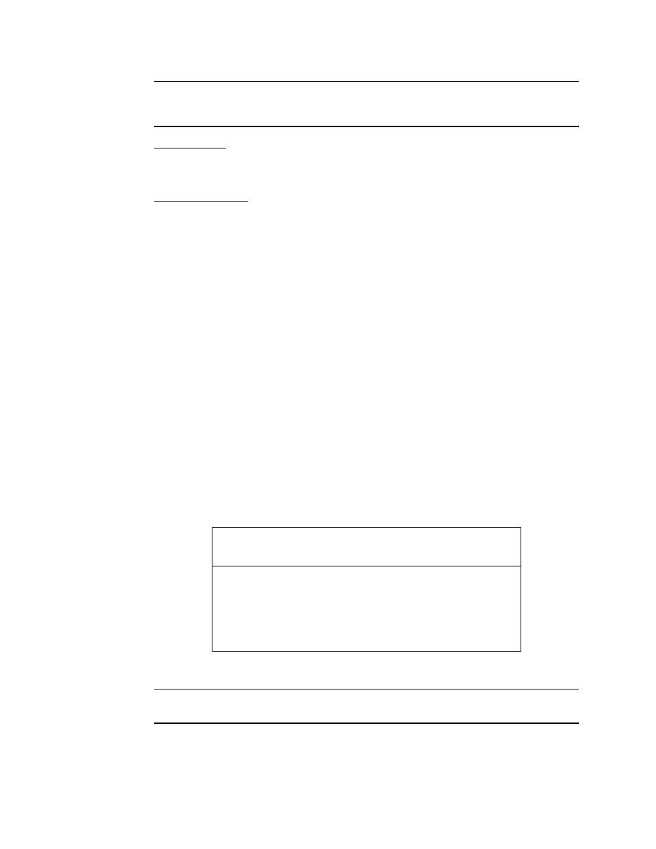
Table 2: Reconnecting the Combustible Gas Detector to the Amplifier
Detector Lead
Amplifier
Interconnect Terminal Strip
Red
SENSOR RED
White
SENSOR WHT
Green
SENSOR GRN
Black
SENSOR BLK