Installation – RKI Instruments 65-2398RK User Manual
Page 9
65-2398RK Combustible Gas Transmitter • 5
junction box. The detector and amplifier are factory installed in the junction box. Three
spacers installed on the back of the junction box control the distance of the junction box
from a mounting surface and ensure that there is enough room to install a calibration cup
on the detector during calibration.
Installation
This section describes procedures to mount the combustible gas transmitter in the
monitoring environment and wire the transmitter to a controller.
Mounting the Combustible Gas Transmitter
1.
Select a mounting site that is representative of the monitoring environment. Consider
the following when you select the mounting site.
•
Select a site where the transmitter is not likely to be bumped or disturbed. Make
sure there is sufficient room to perform start-up, maintenance, and calibration
procedures.
•
Select a site where the target gas is likely to be found first. For lighter gases,
mount the detector near the ceiling; for heavier gases, mount the detector near the
floor.
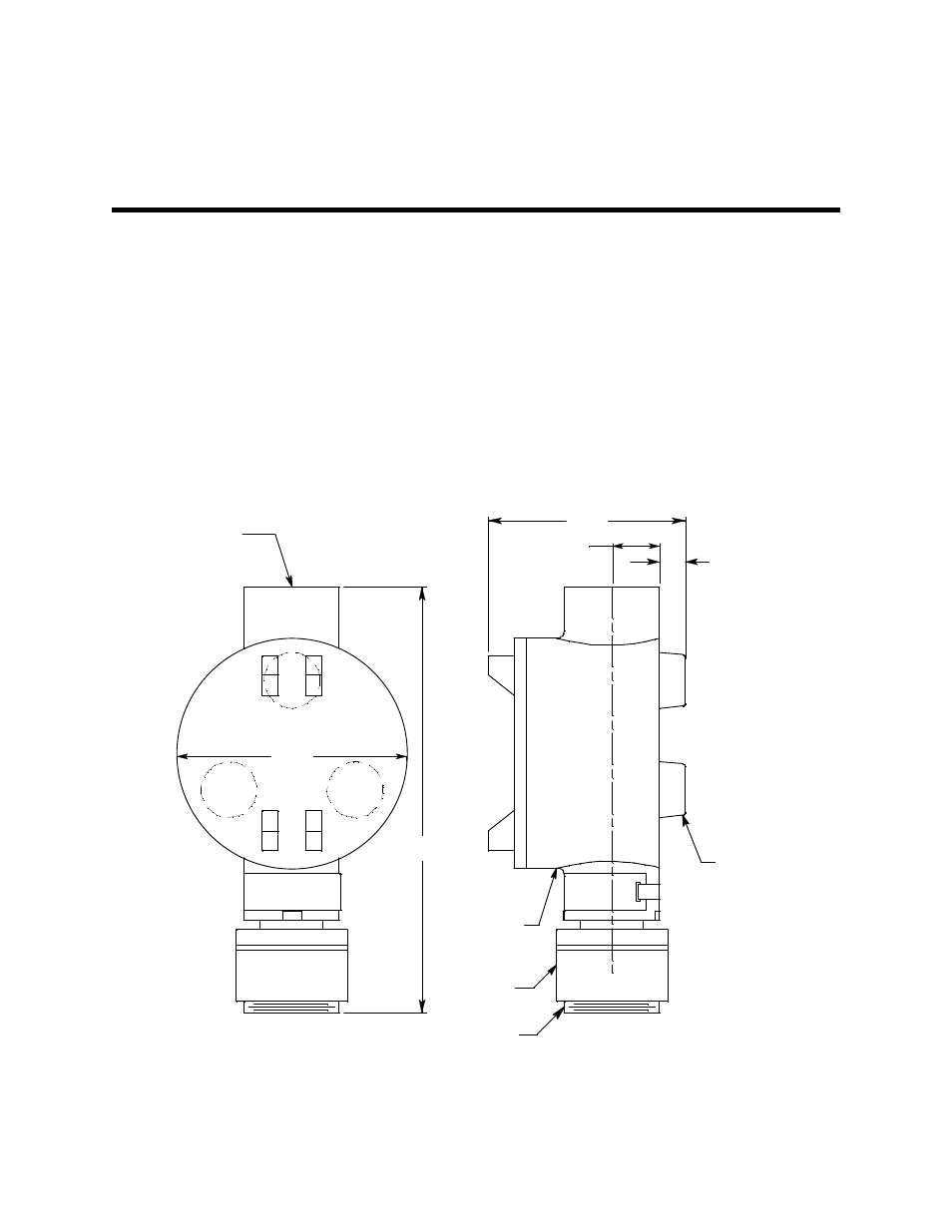
Figure 3: Mounting the Combustible Gas Transmitter
2.
At the monitoring site you select, hang or mount the junction box with the detector
Rubber
Spacers,
3X
3.10
.75
.38
3.65
3/4 NPT
Female
IR LEL
Detector
1 1/2-20 Thread for
Calibration Cup
J-Box
6.80 MAX