Installation – RKI Instruments 61-1007RKSS User Manual
Page 8
4 • 61-1007RKSS Carbon Dioxide Gas Detector
connect the wiring from the detector to a controller. An O-ring seals the interface between
the junction box cover and the junction box base.
The terminal block within the junction box facilitates the wiring process. A cover on the
front of the junction box allows access to the interior of the junction box. A locking set
screw on the junction box cover allows you to secure the junction box cover and prevent it
from being removed.
Installation
This section describes procedures to mount the CO
2
detector in the monitoring
environment and wire it to a controller.
Mounting the CO
2
Detector
1.
Select a mounting site that is representative of the monitoring environment. Consider
the following when you select the mounting site.
•
Select a site where the detector is not likely to be bumped or disturbed. Make sure
there is sufficient room to perform start-up, maintenance, and calibration
procedures.
•
Select a site where the target gas is likely to be found first.
•
Select a site that minimizes the possibility of someone breathing on the detector.
The exhaled CO
2
may cause an alarm.
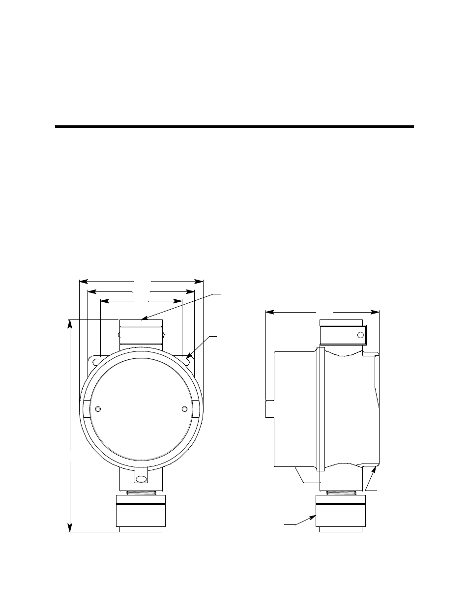
Figure 3: Outline and Mounting Dimensions
.20 Dia. x
.45 Slot, 2X
3.34
3/4 NPT
Female, 2X
J-Box
3.15
2.4
IR CO2 Detector
3.66
6.80 MAX