Overview, Specifications – RKI Instruments 35-3001-06-01 User Manual
Page 5
35-3001-06-01 Combustible Gas/Oxygen Sample-Draw Detector • 1
Overview
This operator’s manual describes the 35-3001-06-01 combustible gas/oxygen sample-draw
detector. This manual also describes how to install, start up, maintain, and calibrate the sample-
draw detector when using it with a gas monitoring controller. A parts list at the end of this manual
lists replacement parts and accessories for the sample-draw detector.
Specifications
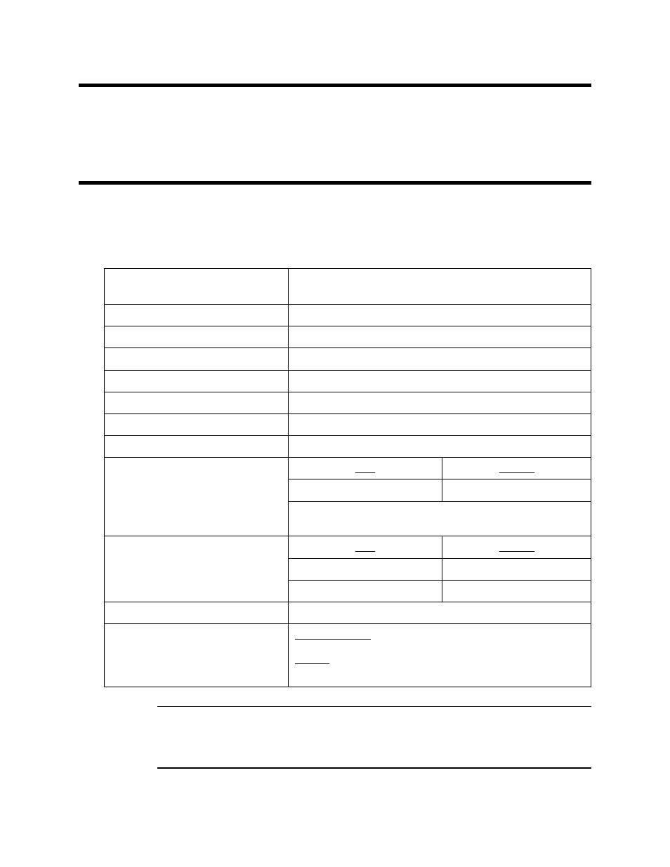
Table 1 lists specifications for the combustible gas/oxygen sample-draw detector. See the controller
Operator’s Manual for information specific to the controller.
WARNING:
When using the 35-3001-06-01, you must follow the instructions and warnings in
this manual to assure proper and safe operation of the 35-3001-06-01 and to
minimize the risk of personal injury. Be sure to maintain and periodically
calibrate the 35-3001-06-01 as described in this manual.
Table 1: Specifications
Target Gases and Detection Range
Combustible gas: 0 - 100% LEL
Oxygen: 0 - 25% volume
Input Power
24 VDC Nominal (18.5 VDC - 30 VDC)
Construction (housing)
Fiberglass/polyester (NEMA 4X)
Dimensions
8.5 in. H x 6.5 in. W x 4.25 in. D
Weight
4.5 lbs.
Sampling Method
Sample-draw
Sample Flow
3.0 SCFH typical, with no inlet or exhaust line
Flow to Sensor
1.0 SCFH (nominal)
Maximum Recommended Inlet/
Exhaust Line Length for
1/4” O.D. x 1/8” I.D. Tubing
Inlet
Exhaust
50 feet
0 feet
* RKI Instruments, Inc. does not recommend installing this tubing
size on both the inlet and exhaust.
Maximum Recommended Inlet/
Exhaust Line Length for
1/4” O.D. x 0.170” I.D. Tubing
Inlet
Exhaust
50 feet
50 feet
75 feet
0 feet
Response Time
90% in 30 seconds
Accuracy
Combustible Gas:
± 5% of reading or ± 2% of full scale (whichever is greater)
Oxygen:
± 0.5% O
2