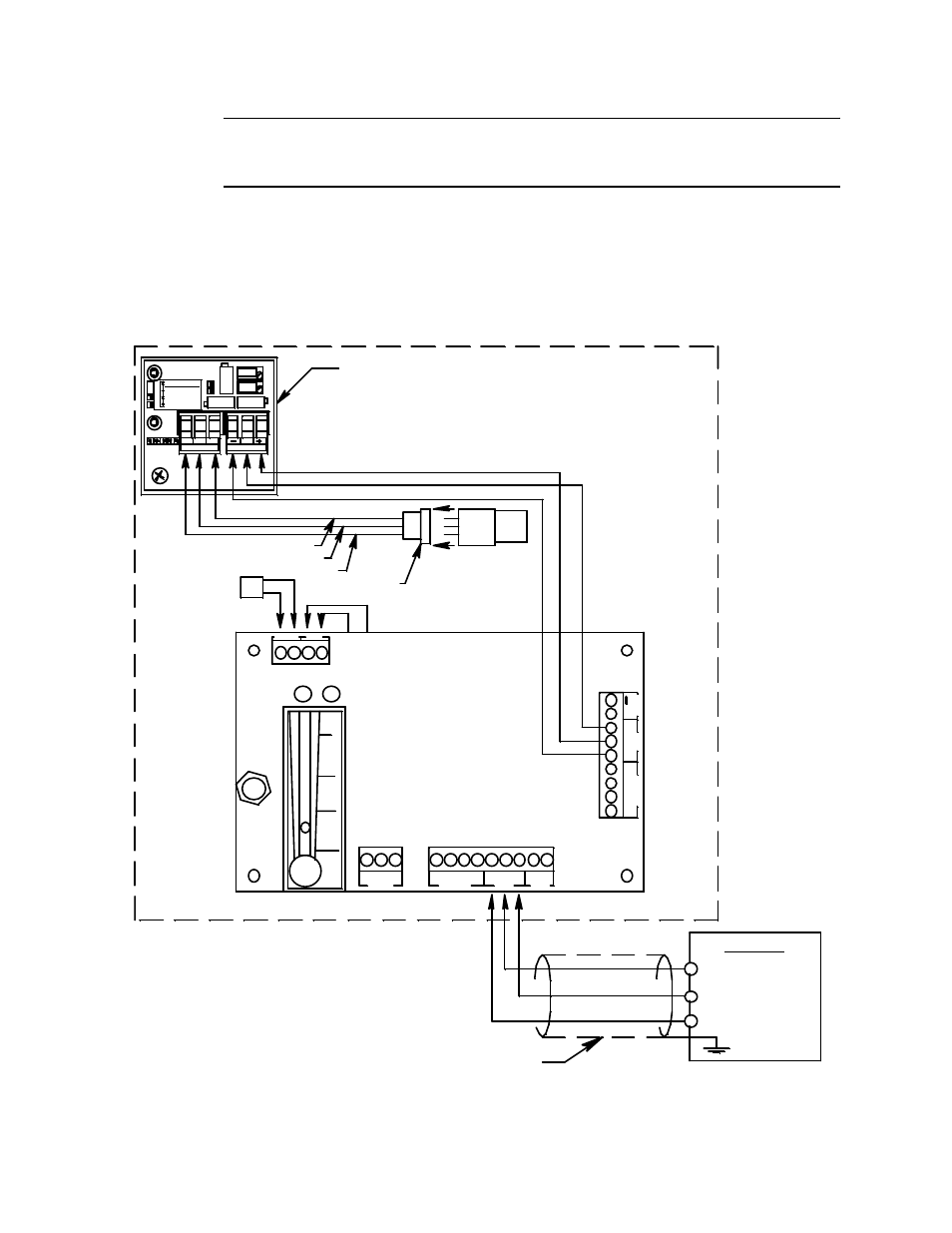
Sample draw housing, Main pcb, Figure 4: internal and field wiring diagram – RKI Instruments 35-3000RKA-10 User Manual
Page 12: Controller, Dcground)
12 • 35-3000RK-10 PPM Hexane Sample Draw Detector
CAUTION: If using shielded cable, leave the cable’s drain wire disconnected and
insulated at the sample draw detector. You will connect it to an available
chassis ground at the controller.
7.
Route the shielded cable or wires in conduit leading from the sample draw detector to
the controller.
8.
Connect the cable’s drain wire to an available chassis ground at the controller. A
ground stud is typically a convenient location to connect to chassis ground in an RKI
controller.
Figure 4: Internal and Field Wiring Diagram
+
24V
GN
D
BL
K
GR
N
4
/2
0
P-
A
M
P
AM
P
4/20 ( S)
- (DCGround)
24V ( +)
GND ( -)
Detector i n
Sam pl e Cham ber,
Factor y W ired
Cable Shield
S (4 - 20mA In)
+ 24 VDC
Controller
P- AMP
AMP
LEL/ O2
GRN
PSW
PUMP
+
_
4/20
24V
GND
BLK
WH T
Pum p,
Factor y W ired
1- 2 He x
3- 4 H2
Ga s Sel ect
1
3
4
2
W
B
R
D ETECTOR
SPAN
ZERO
P WR/ SIG
S
W hi te
Red
Bl ac k
Detector S oc ket
LE
L/
O
2
WH
T
RD
GND
115V AC
N
H
Amplifier , Factor y W ired
Sample Draw Housing
RD
Main PCB
Pr essure S wi tch,
Factor y W i red
115 V AC In
Stri p Not Used
i n This V ersi on