Description, Housing – RKI Instruments 35-3000RK-OXY User Manual
Page 5
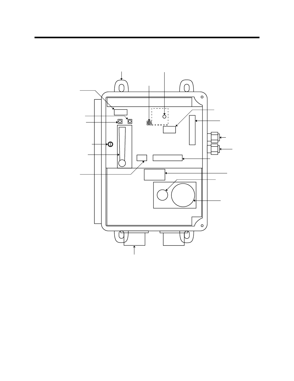
35-3000RK-OXY Sample-Draw Oxygen Detector • 5
Description
This section describes the components of the sample-draw oxygen detector. The sample-
draw detector consists of the housing, flow system, and detection system.
Figure 1: Sample-draw Oxygen Detector Component Location
Housing
The sample-draw detector’s fiberglass housing is weather- and corrosion-resistant. It is
suitable for installation where general purpose equipment is in use.
The housing door is hinged on the left side and is secured by two latches on the right side.
The flowmeter and status lights are visible through a window in the housing door.
Four mounting feet are attached to the back of the housing (one at each corner). Use the
mounting feet to install the housing to a vertical surface. Use the two conduit hubs on the
bottom of the housing to make wiring connections.
An aluminum subpanel is mounted to the interior of the housing. The sample-draw
detector’s internal components are mounted to the subpanel.
Pump
terminal strip
Mounting foot
(total of 4)
Flow adjust
potentiometer
Low flow
potentiometer
Pilot light
Fail light
Relay
Detector
terminal strip
EXHAUST fitting
INLET fitting
Interconnect terminal strip
Filter
Combustible gas sensor
Oxygen sensor
Conduit hub
(total of 2)
Bypass valve
Power
terminal strip
(not used)
Flowmeter
(not used in this version)