RKI Instruments 35-3000RK-OXY User Manual
Page 11
35-3000RK-OXY Sample-Draw Oxygen Detector • 11
CAUTION:
If using shielded cable, leave the cable’s drain wire insulated and disconnected at the
sample-draw detector. You will connect the opposite end of the drain wire at the
controller.
7.
Route the cable or wires in conduit leading from the sample-draw detector through
one of the conduit hubs on the controller.
CAUTION:
At the controller, do not route controller power and sample-draw detector wiring
through the same conduit hub. The controller power cable may disrupt the
transmission of the sample-draw detector signal to the controller.
8.
Connect the wires to the applicable detector terminal strip and power terminals at the
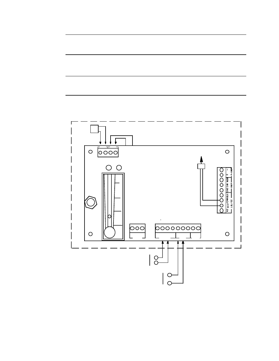
controller as shown in Figure 4.
Figure 4: Wiring the Sample-Draw Oxygen Detector to a Controller
5.
Connect the cable shield to an available chassis ground. The grounding screw on one
of the controller’s grounded conduit hubs is an example of a chassis ground.
4/20
White
Green
To Oxygen
Sensor
WHT GRN BLK GND 24V
+
_
LEL/ O2
AMP
P- AMP
Pump,
Internally
Wired
PUMP
PSW
GND
H
Controller Terminals
O r Power Supply
N o tU s e dOn
ThisVersion
Controller Oxygen
Detector Terminals
Green (-)
White (+)
N
115VAC
- (DC Ground)
+( 23 VDC - 28 VDC)
PCB in Single Point
Sample- Drawing
Detector
Pressure Switch,
Internally Wired
OxygenSample Draw Housing
RD