Internal description, Display screens – RKI Instruments Beacon 800 User Manual
Page 7
Beacon 800 Gas Monitor Operator’s Manual
Internal Description • 4
Internal Description
This section describes the internal components of the Beacon 800.
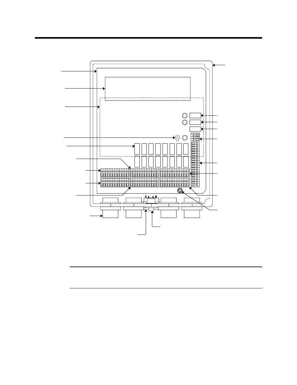
Figure 1: Beacon 800 Gas Monitor Component Location
Display Screens
NOTE: The display screens, status lights, and program buttons are mounted to a
secondary circuit board. This circuit board is mounted to the main circuit board by
standoffs.
The display screens simultaneously display the target gas, measuring unit, and current
gas reading of all active channels. The top screen displays channels 1 through 4; the
bottom screen displays channels 5 through 8.
The display screens also display messages, settings, and other data when you are
operating the configuration menu.
Housing
AC terminal strip
Controller
terminal strip
Alarm 2 common relay
Alarm 1 common relay
Fail common relay
Conduit hub
(total of 4)
Reset switch
Buzzer
(behind switch)
Power supply
Display board
(see Figure 2)
Power switch
Channel relays
(see Figure 3)
Transmitter terminal strip
(channels 5-8)
Transmitter terminal strip
(channels 1-4)
Alarm terminal strip
(channels 5-8; alarm 2)
Alarm terminal strip
(channels 5-8; alarm 1)
Alarm terminal strip
(channels 1-4; alarm 1)
Alarm terminal strip
(channels 1-4; alarm 2)
Main board
(shown without door)
Ground Stud