PLX Devices M-300 TE User Manual
Page 3
Users Guide: iMFD Sensor Module
Version 1.0 May 1, 2008
www.plxdevices.com
(408)745-7591
Connecting Power to the Unit:
CAUTION! CONNECTING THE M-300TE IN REVERSE POLARITY WILL
DAMAGE THE UNIT! CHECK CONNECTIONS BEFORE POWERING ON.
1. The M-300TE accepts 12-18V DC for power. Connect the negative wire (black) to your vehicle’s ground. This is usually the
negative terminal of your automobile’s battery. Connect the positive wire (red) to your vehicle’s ignition power. This power
is only supplied when your key is turned passed a specific position and is off when your key is removed. Your power
connection must be capable of supplying at least 3 amps of current. A 5-7 Amp fuse is recommended for safety.
*If you plan to integrate the M-300TE Plug and Play with other aftermarket devices by utilizing the analog output signal wires. Make
sure that the negative wire (black) is connected as close as possible to your device's ground. This guarantees that both devices "see"
the same reference ground and a more accurate interpretation of the output voltages will be achieved. Please refer to the PLXApp
notes online for more information.
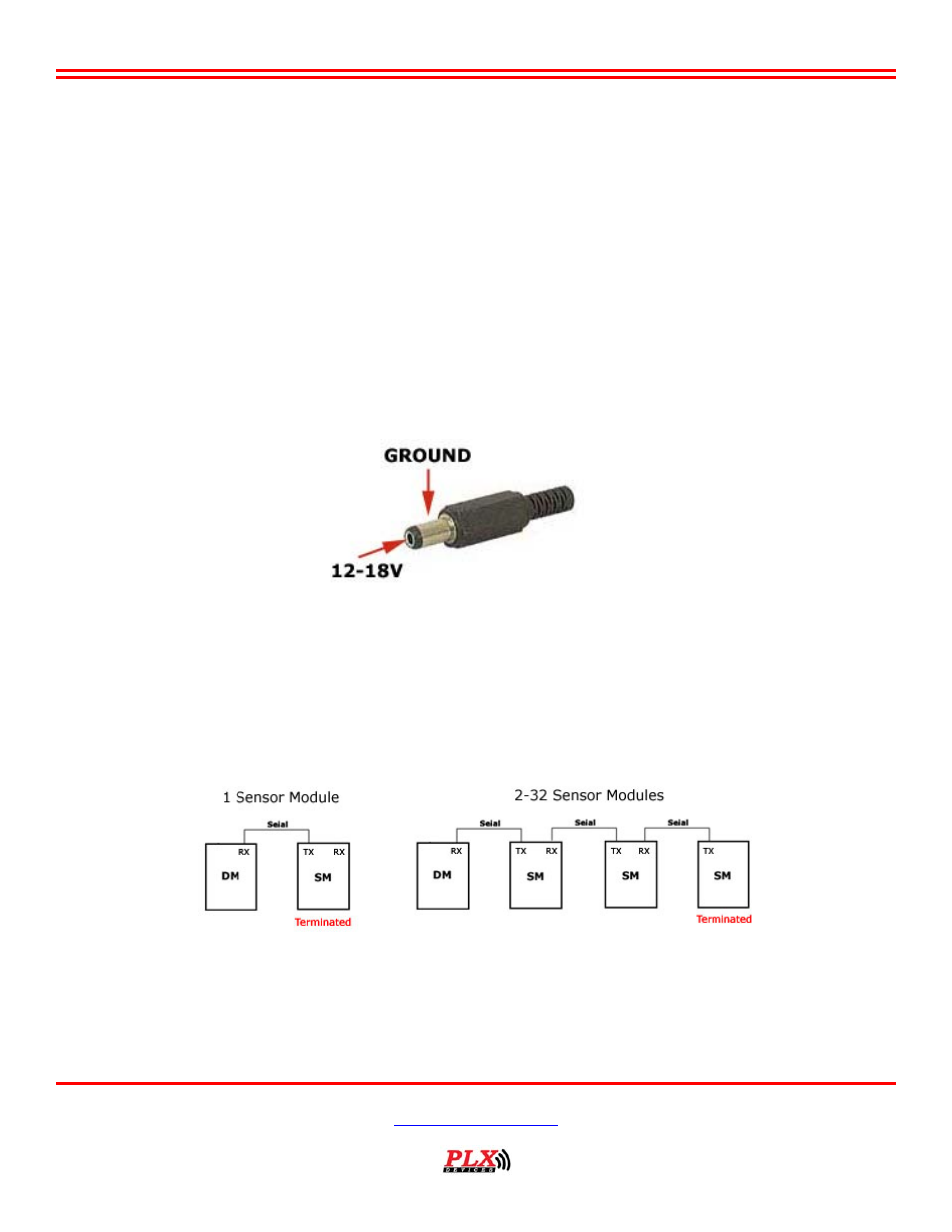
2. Locate the 2.1mm Power plug. Unscrew the plastic cover and insert it into the red/black power wires.
3. Solder or crimp the red power wire to the CENTER of the connector. (12-18V)
4. Solder or crimp the black power wire to the SHIELD of the connector. (GROUND)
(Figure 3)
5. The unit takes approximately 60 seconds for the oxygen sensor to heat up and produce accurate measurements.
6. Sensor calibration is not needed. The M-300TE is self calibrating and no user intervention is required.
Using the Sensor Module in the iMFD Chain:
1. M-300TE is also a SM sensor module, just as SM-AFR as a sensor module in daisy chain.
2.
If the M-300TE is the only sensor module or last sensor module in the iMFD chain, be sure to have the termination jumper
installed. Otherwise, remove the jumper. Please refer to (Figure 1) for the location of the termination jumper.
(Figure 4)