Omnitron Systems Technology iConverter CWDM/X User Manual
Page 2
Channel Port
The Channel Ports transmit and receive signals on specific CWDM wavelengths. The
Channel Ports are multiplexed onto and demultiplexed from the Common Port.
Common Port
The Common Port (COM) transmits and receives the aggregated wavelengths
connected to the Channel, Expansion and 1310 Pass Band Ports.
1310 Pass Band Port
The 1310 Pass Band Port (1310PB) allows a legacy 1310nm signal to pass through
the CWDM/X module on a reserved band (1260nm to 1360nm). The port can be
used to combine an existing legacy 1310nm network with up to 8 CWDM channels,
allowing the CWDM channels in the range of 1470nm to 1610nm to be overlaid
on the same fiber pair as the existing 1310nm network. Figure 3 illustrates two
CWDM/X modules with the 1310 Pass Band Port option.
COMMON
1470
1490
1590
1610
1310 PB
8860-1
1470
1490
1590
1610
1310 PB
8860-1
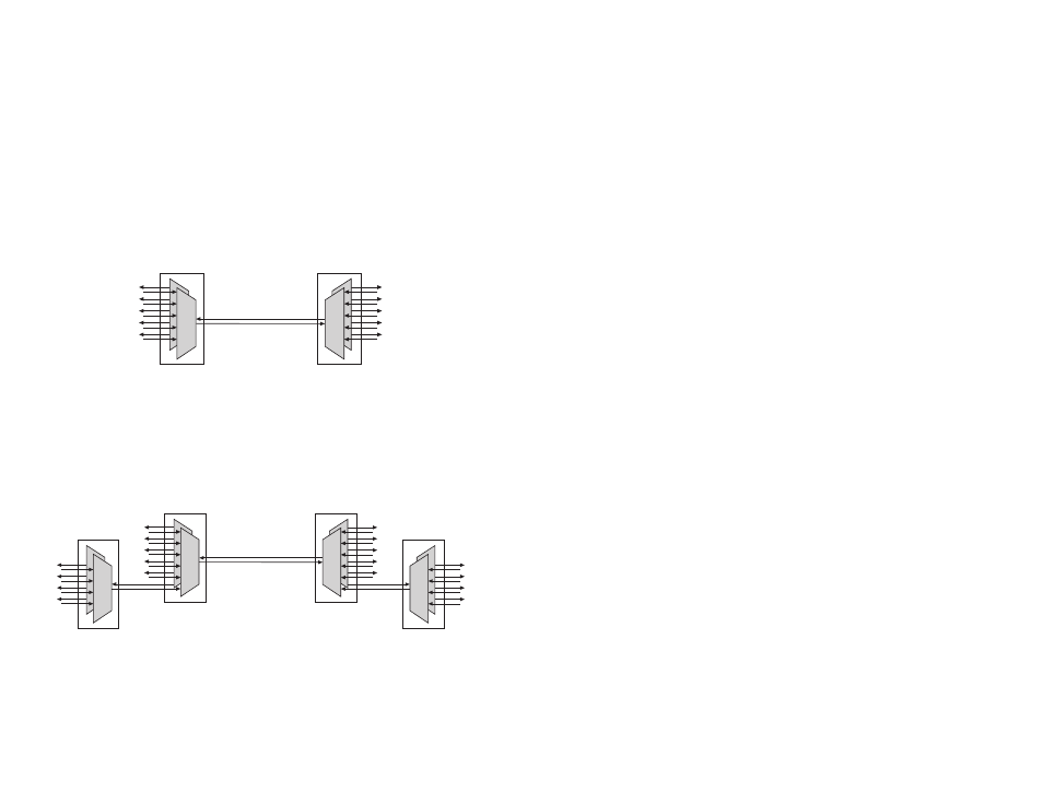
Figure 3: 4-Channel MUX/DEMUX
Expansion Port
The Expansion Port (EXP) enables the cascading of two CWDM/X modules as
shown in Figure 4. On models 8860-2 and 8860-3, the Expansion Port can also
be used as a 1550nm Pass Band Port to transport legacy 1550nm single-mode
traffic as long as the spectral width of the1550nm legacy network is between 1510
and 1570nm.
1510
1530
1550
1570
EXP
COMMON
1470
1490
1590
1610
1310 PB
8860-2
8861-0
1510
1530
1550
1570
EXP
1470
1490
1590
1610
1310 PB
8860-2
8861-0
COM
COM
Figure 4: Two Cascaded 4-Channel MUX/DEMUX
Only the 4-Channel CWDM/X module is available with an optional Expansion
Port.
8-Channel CWDM/X MUXes require the use of the Band Splitter (8865-0) to multiplex
16 channels over the Common Port.
Page 2
Installation
1. Carefully slide the module into an open slot in an iConverter chassis. Align
the module with the installation guides and ensure that the module is firmly
seated against the backplane. Secure the module by fastening the front panel
thumbscrew(s) (push in and turn clockwise to tighten) to the chassis front.
The CWDM/X module requires no external power, however, if management is
required, the module must be installed in an iConverter powered chassis with
a Network Management Module (NMM2 Model 8000N-0) or a media converter
with integrated management (such as the iConverter 10/100M2)*.
2. Connect a single-mode, dual fiber duplex LC cable between the Channel Port of
the CWDM/X module and the attached device. It is important to ensure that the
wavelength of the CWDM/X matches the wavelength of the attached device.
Connect all Channel Ports in this manner. Ensure that the transmit (Tx) is
attached to the receive side of the device at the other end, and the receive (Rx)
is attached to the transmit side.
3. Connect a single-mode, dual fiber duplex LC cable between the Common Ports
on the CWDM/X modules (this connection may be made through fiber patch
panels since the modules may not be co-located). Ensure that the transmit (Tx)
is attached to the receive side of the device at the other end, and the receive
(Rx) is attached to the transmit side.
4. When cascading two 4-Channel CWDM/X modules, connect a single-mode,
dual fiber duplex LC cable between the Common Port on one CWDM/X module
and the Expansion Port on the other CWDM/X module (see Figure 5). Ensure
that the transmit (Tx) is attached to the receive side of the device at the other
end, and the receive (Rx) is attached to the transmit side.
5. When overlaying a CWDM channel on an existing 1310nm legacy network,
connect the single-mode, dual fiber duplex LC cable from the legacy network
to the 1310 Pass Band Port on the CWDM/X module. Ensure that the transmit
(Tx) is attached to the receive side of the device at the other end, and the
receive (Rx) is attached to the transmit side.
NOTE: The iConverter CWDM/X modules can not be installed in slots 4, 8, 12 and
16 of a 19-Module Chassis or in the top slot of a 2-Module Chassis or in a 1-Module
Redundant Power Chassis.
NOTE: The iConverter 8-Channel Double-Wide CWDM/X can only be installed
in a 2-Module Chassis or 19-Module Chassis with the exception of slots 4/5, 8/9,
12/13 and 16/17.
*For complete management functionality, use M2 series (NMM2, GX/TM2, 2GXM2.
10/100M2, 2FXM2) or higher.
Page 3