Mq sp2 ce saw — operation – Multiquip SP2 SCE20H20 User Manual
Page 32
PAGE 32 — MQ SP2 CE SAW — OPERATION & PARTS MANUAL — REV. #6 (09/08/06)
Saw Alignment
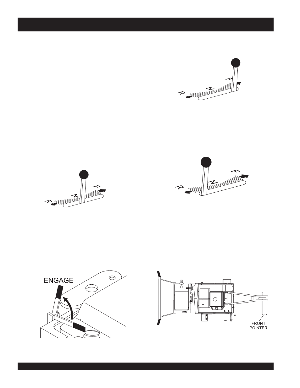
1. The SP2 CE saw employs a front pointer (Figure 42) that has
been precisely aligned with the diamond blade at the factory.
Referencing the figure below, accurate tracking is accom-
plished by referencing the front pointer tip over the cut line.
Precise saw direction is accomplished by slight operator
pressure against the handle bars.
Figure 42. Saw Pointer
2. To reorient a pointer position, loosen the screw that secures
the pointer bar to the shaft, adjust as necessary, and retighten
the screw.
MQ SP2 CE SAW — OPERATION
Traveling During Cutting (Self-Propelled)
Self-propelled models of the SP2 CE saw have a hydrostatic
transmission which mechanically propels the saw during cutting
operations. To prepare the machine for self-propelled cutting:
1.
Place the
travel lever in the NEUTRAL position.
Figure 39. Transmission Engage/Disengage Lever
(Engage Position)
3.
Move the
travel lever towards the FORWARD position to
increase forward travel speed during cutting (Figure 40).
Placing the travel lever fully forward will move the saw at
maximum speed.
2.
Lift the
transmission
engage/disengage lever,
located on the console (Figure 39). Leaving the lever down
disengages the transmission to allow for manual pushing
during cutting or moving the machine around the job site.
Figure 38. Transmission Engage/Disengage Lever
(Neutral Position)
Figure 40. Transmission Engage/Disengage Lever
(Forward Position)
4.
When reverse movement is required, move the
travel lever
towards the REVERSE position (Figure 41). Placing the
travel lever fully in reverse will move the saw backwards at its
maximum reverse speed.
Figure 41. Transmission Engage/Disengage Lever
(Reverse Position)
5. When the end of the cut has been reached, use the raise/
lower crank on the console to raise the blade out of the cut.
6. When cutting is complete, turn the engine OFF using the
ENGINE STOP TOGGLE SWITCH on the handlebars, and
wait for the blade to stop rotating.
7. Set the engine ON/OFF switch to the OFF position.
8. Place the water valve in the OFF position (as required).
9. Push the Wheel Clamp Levers downward to apply braking
pressure to the wheels (Figure 37).