Lifting the trowel onto a slab, Heavy duty extension cord, Emergency stop switch – Multiquip EPOXY/M SERIES User Manual
Page 28: Correct, Connect one end of a, Make sure to connect the
PAGE 28 —EPOXY SERIES WALK-BEHIND TROWEL— OPERATION AND PARTS MANUAL — REV. #5 (10/06/10)
EPOXY/M SERIES TROWEL — INITIAL START-UP (ELECTRIC MOTOR)
Starting The Electric Motor (Single Phase 115/230 Volts)
The electric motor used on the B-Series trowel has two operating
voltages:
■ 115 VAC Single Phase, 2 Horsepower
■ 230 VAC Single Phase, 2 horsepower
1. Lift the trowel onto the slab in the same manner as described
on page 24 ("
Lifting the Trowel Onto a Slab
").
2. Connect one end of a
heavy duty extension cord
to the
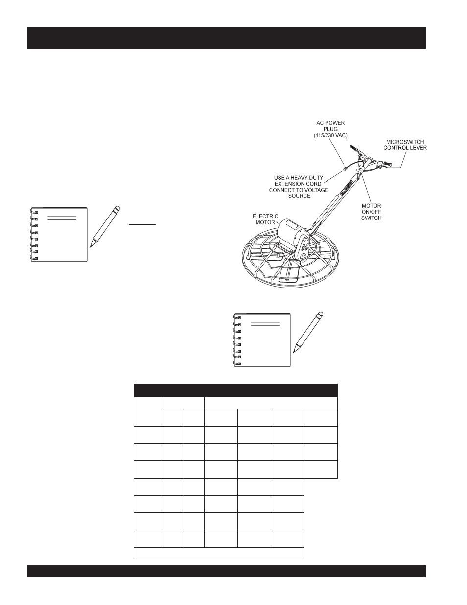
AC power plug on the trowel.
3. Connect the other end of the extension cord to an AC power
source.
Extension Cable
When electric power is to be provided to the trowel at some
distance from the power source, extension cords are normally
used. Cables should be sized to allow for distance in length and
amperage so that the voltage drop between the power source
and point of use (trowel) is held to a minimum. Use the cable
selection chart (Table 4) as a guide for selecting proper extension
cable size.
At 115 VAC the motor should
draw about 16.6 amps and at
230 VAC the motor should draw
about 8.4 amps.
Figure 26. Electric Motor Trowel
4. Squeeze the micro-switch lever ( Figure 26) to begin trow-
eling. This lever will act an
emergency stop switch
. When
this lever is released, voltage to the electric motor will be
interrupted. When this lever is squeezed the voltage will
resume. This can only be accomplished if the trowel's power
ON/OFF switch is in the ON position.
)
n
o
i
t
a
r
e
p
O
e
s
a
h
P
e
l
g
n
i
S
,
z
H
0
6
(
n
o
i
t
c
e
l
e
S
e
l
b
a
C
.
4
e
l
b
a
T
n
i
t
n
e
r
r
u
C
s
e
r
e
p
m
A
s
t
t
a
W
n
I
d
a
o
L
h
t
g
n
e
L
e
l
b
a
C
e
l
b
a
w
o
ll
A
m
u
m
i
x
a
M
0
2
1
t
A
s
t
l
o
V
0
4
2
t
A
s
t
l
o
V
e
r
i
W
0
1
#
e
r
i
W
2
1
#
e
r
i
W
4
1
#
e
r
i
W
6
1
#
5
.
2
0
0
3
0
0
6
.t
f
0
0
0
1
)
m
5
0
3
(
.t
f
0
0
6
)
m
3
8
1
(
.t
f
5
7
3
)
m
7
0
1
(
.t
f
0
5
2
)
m
6
7
(
5
0
0
6
0
0
2
1
.t
f
0
0
5
)
m
2
5
1
(
.t
f
0
0
3
)
m
1
9
(
.t
f
0
0
2
)
m
1
6
(
.t
f
5
2
1
)
m
8
3
(
5
.
7
0
0
9
0
0
8
1
.t
f
0
5
3
)
m
7
0
1
(
.t
f
0
0
2
)
m
1
6
(
.t
f
5
2
1
)
m
8
3
(
.t
f
0
0
1
)
m
0
3
(
0
1
0
0
2
1
0
0
4
2
.t
f
0
5
2
)
m
6
7
(
.t
f
0
5
1
)
m
5
4
(
.t
f
0
0
1
)
m
0
3
(
5
1
0
0
8
1
0
0
6
3
.t
f
0
5
1
)
m
6
4
(
.t
f
0
0
1
)
m
0
3
(
.t
f
5
6
)
m
9
1
(
0
2
0
0
4
2
0
0
8
4
.t
f
5
2
1
)
m
8
3
(
.t
f
5
7
)
m
2
2
(
.t
f
0
5
)
m
5
1
(
0
3
0
0
6
3
0
0
2
7
.t
f
5
7
)
m
3
2
(
.t
f
0
5
)
m
5
1
(
.t
f
5
3
)
m
1
1
(
.
e
g
a
tl
o
v
w
o
l
m
o
r
f
tl
u
s
e
r
n
a
c
e
g
a
m
a
d
t
n
e
m
p
i
u
q
E
:
N
O
I
T
U
A
C
Make sure to connect the
correct
AC voltage (115 or
230 VAC) to the electric motor.
Connecting an incorrect
voltage could cause serious
damage to the electric motor.
The identification plate located
on the motor will indicate the
motor's voltage requirement.
NOTE
NOTE