Ja-series trowel — assembly and installation – Multiquip JA-SERIES User Manual
Page 20
PAGE 20 — JA-SERIES WALK-BEHIND TROWEL— OPERATION AND PARTS MANUAL — REV. #9 (07/02/10)
JA-SERIES TROWEL — ASSEMBLY AND INSTALLATION
Handle Height Adjustment
If handle height adjustment is desired, a handle wedge kit can be
purchased for your trowel by ordering P/N 2576 from your Multiquip
dealer. These wedges are placed between the handle and the
gearbox to adjust the operating height of the handle. This kit
comes complete with wedges, new bolts and installation
instructions. This will move your operating handle position up or
down approximately 3” (76mm).
Safety Kill Wire
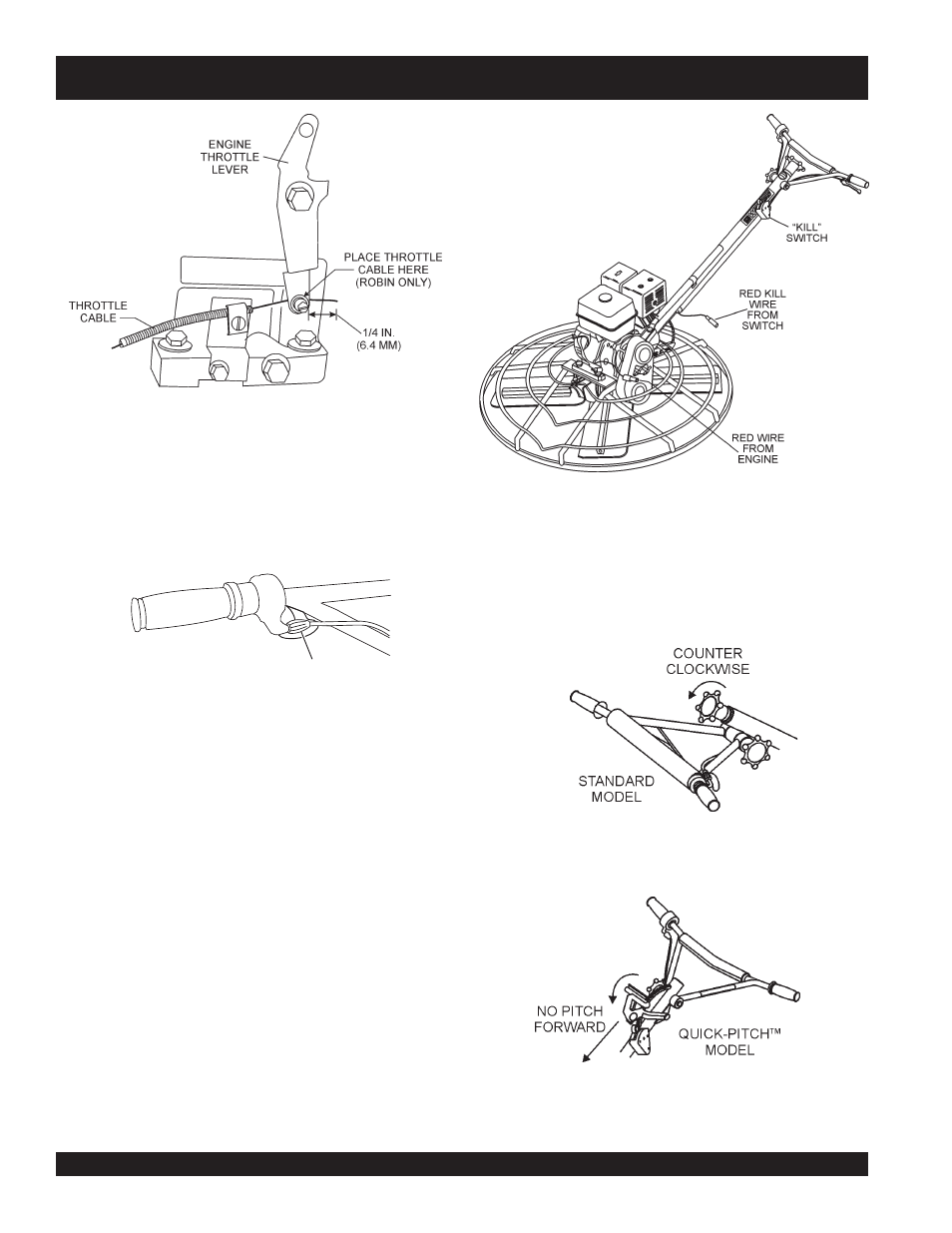
Locate the
RED
wire protruding from the handle tube (Figure11)
and connect it to the
RED
tail wire on the engine. Test the kill
switch to insure proper operation.
Figure 11. Engine Kill Wire Connection
Figure 12. "No Pitch" Position (Standard)
Figure 13. "No Pitch" Position (Quick-Pitch™)
1.
Expose the pitch cable to maximum by adjusting the handle
pitch to the "no pitch" position. On the standard model turn
the pitch control counter-clockwise, (Figure 12). On the
Quick-Pitch™ model, pivot the pitch handle forward or no
pitch, (Figure 13).
Figure 9. Throttle Cable Connection (ROBIN)
7. These are general instructions. Installation of the throttle
cable may vary for different engine configurations. Please
look for more detailed instructions inside the box containing
the handle. These more detailed instructions should provide
adequate guidance for installing.
4.
Tighten cable clamp screw and swivel stop screw.
5.
After the cable has been installed on the engine, adjust
and tighten operator position of the handle to lock the
throttle cable at the proper length.
6.
Adjust cable tension by rotating the barrel adjuster. (Figure
10)
Pitch Cable Installation
BARREL ADJUSTER
Figure 10. Barrel Adjuster