Ca4hc trowel — maintenance, Caution – Multiquip CA4HC User Manual
Page 29
CA4HC WALK-BEHIND TROWEL — OPERATION MANUAL — REV. #0 (09/29/06) — PAGE 29
Changing Blades Only
We recommend that
all the blades be changed at the
same
time
. The machine may wobble or bounce if only some of the
blades are changed at one time.
1. Place the machine on a flat, level surface. Adjust the blade
pitch control to make the blades as flat as possible. Note the
blade orientation on the trowel arm.
Before removing the
blades, please note the
orientation of the blade on
the trowel arm.
1. Remove the two bolts and lock washers that secure the blade
to the trowel arm. Remove the blade.
2. Using a wire brush, scrape all concrete particles and foreign
debris from the trowel arm.
3. Install the new trowel blade onto the trowel arm. Make sure
blade is installed correctly, maintaining the proper orienta-
tion for direction of rotation.
4.
Reinstall
the two bolts and lock washers that secure the
blade to the trowel arm. Tighten both bolts securely.
5. Repeat steps 1 - 4 for all remaining blades.
NOTE
CA4HC TROWEL — MAINTENANCE
Re-Assembly
1. Clean and examine the upper/lower wear plates and thrust
collar. Examine the entire spider assembly. Wire brush any
concrete or rust build-up. If any of the spider components are
found to be damaged or out of round, replace them.
2. Make sure that the bronze trowel arm bushing is not damage
or out of round. Clean the bushing if necessary. If the bronze
bushing is damaged or worn, replace it.
3. Reinstall bronze bushing onto trowel arm.
4. Repeat steps 2 -3 for each trowel arm.
5. Make sure that the spring tensioner is in the correct position
to exert tension on the trowel arm.
6. Insert all trowel arms with levers into spider plate (with bronze
bushing already installed) using care to align grease hole on
bronze bushing with grease hole fitting on spider plate.
7. Lock trowel arms in place by tightening the hex head bolt with
zerk grease fitting and jam nut.
8. Re-install the blades onto the trowel arms.
9. Install stabilizer ring onto spider assembly.
10. Lubricate all grease points (zerk fittings) with premium
"
Lithum 12"
based grease, conforming to NLG1 Grade #2
consistency.
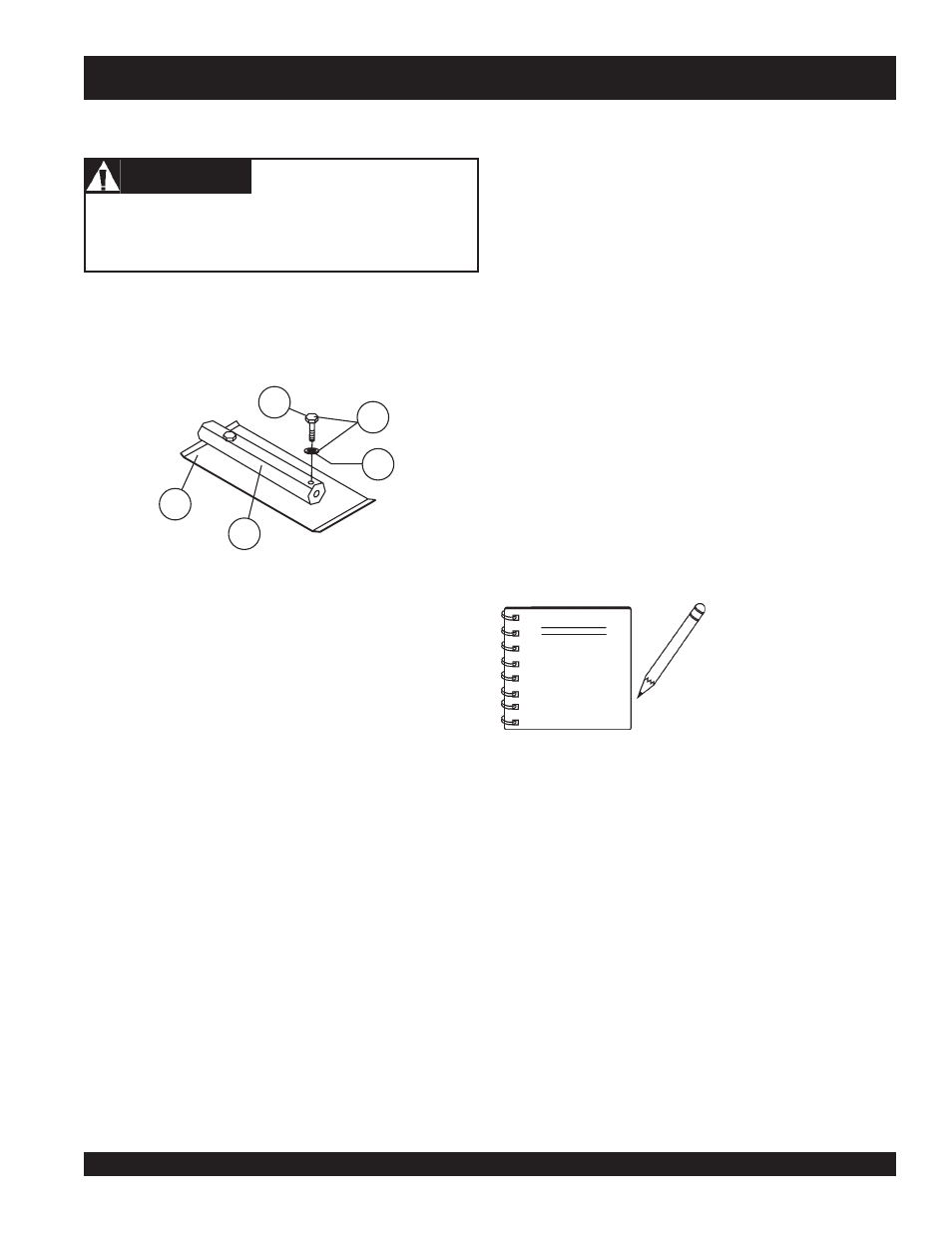
1. Remove the trowel blades from the trowel arm by removing
the two hex head bolts (Figure 34) from the trowel arm. Set
blades aside.
Figure 34. Trowel Blades
2.
Wire brush
any build-up of concrete from all six sides of the
trowel arm. Repeat this for the remaining three arms.
CAUTION
CAUTION
CAUTION
CAUTION
CAUTION
Disconnect the spark plug wire from the spark plug and
secure away from the engine before performing
maintenance or adjustments on the machine.
Trowel Blade Removal
1
Blade
2
Blade Arm
3
Hex Head Bolt
4
Lock Washer
4
Remove From Arm
1
2
3
4
5