Control box installation – Multiquip ST41460 User Manual
Page 15
st4/st6 series submersible pumps• operation anD parts manual — rev. #1 (11/12/13) — page 15
ConTrol box insTallaTion
Control box installation
The following procedure outlines the steps for connecting
the pump to a control box.
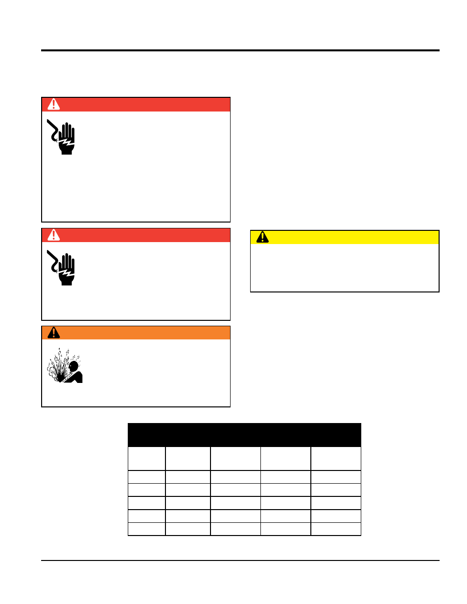
Danger
Each submersible pump is designed to
work with a control box.This control box
contains the necessary electronics (float
switch connections) to operate the pump.
Remember this control box contains
hazardous voltages. Disconnect all sources of power
before installing or servicing. There exists the possibility
of electrocution, electric shock or burn, which can cause
severe bodily harm or even
death!
Danger
When installing the control box, the
possibility exists of electrical shock,
electrocution and possibly death!
never
have untrained personnel perform the
installation.
alWaYs have qualified
service personnel (licensed electrician) perform the
installation.
Warning
Explosion or Fire Hazard exists if this pump
is used with flammable liquids.
Do not use
this pump with
flammable liquids. Do not
install this pump in hazardous locations as
defined by the National Electrical Code,
ANSI/NFPA 70.
Control boX mounting
Mount the control box in an upright vertical position. Make
sure the control box is securely fastened to a flat surface,
that is free of dust, dirt, moisture or any elements that
may contaminate or erode the electronic components of
the control box.
3-phase power installation (input)
Each pump is either configured for 230 or 460 VAC voltage
input. Reference Table 1 for the correct input voltage for
your pump.
If you cannot determine what your pump's power
requirements are, look at the vendor supplied identification
name tag attached to the pump or please contact Multiquip's
Service/Technical Assistance department.
power Cord requirements
When routing the 230/460 VAC, 60 Hz., 3-phase power
via a power cord to the control box,
alWaYs use the
correct wire size. Please refer to Table 5 to determine the
correct wire size. Incorrect wire size can adversely affect
the performance of the pump and may ultimately burn out
the pump motor.
Caution
Applying incorrect power (voltage phasing) to the
submersible pump can cause severe damage to the
pump. Please make sure that the correct voltage and
phase are applied to the pump at all times.
table 5. power Cord length
and Wire size
AMPS
10 Ft.
(3.0 m)
20 Ft.
(6.0 m)
30 Ft.
(9.1 m)
50 Ft.
(15.2 m)
15
12 AWG
10 AWG
8 AWG
6 AWG
20
10 AWG
8 AWG
6 AWG
4 AWG
25
10 AWG
6 AWG
6 AWG
4 AWG
30
10 AWG
6 AWG
4 AWG
2 AWG
40
8 AWG
6 AWG
4 AWG
2 AWG