Figure 1a – Meade Instruments Polaris Series User Manual
Page 4
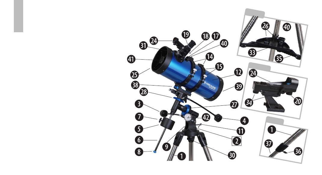
FIGURE 1A
2
Inset C
Inset B
Inset A
1. Tripod legs
2. Large Equatorial Mount
3. Right Ascension control cable
4. Declination control cable
5. Counterweight(s)
6. Counterweight shaft
7. Counterweight lock knobs
8. Counterweight safety knob
9. Latitude adjustment lock (see Fig. 3)
10. Polar axis (see Fig. 3)
11. Latitude adjustment knob
12. Main optical tube (OTA)
13. Optical tube saddle plate (see Fig. 3)
14. Cradle rings
15. Cradle ring lock knobs
16. Red dot viewfinder bracket mounting
thumbscrews (see Fig 4/5)
17. Focuser
18. Focuser thumbscrew
19. Eyepiece
20. Red dot viewfinder On/Off switch
(see Inset B)
21. Declination axis (see Fig. 3)
22. Right Ascension lock (see Fig. 3)
23. Declination lock (see Fig. 3)
24. Red dot viewfinder
25. Front dust cover (not shown)
26. Eyepiece holder slots (see Inset A)
27. Right Ascension setting circle
28. Declination setting circle
29. Latitude dial (see Fig. 3)
30. Azimuth lock
31. Focus knobs
32. Azimuth base (see Fig. 3)
33. Accessory tray (see Inset A)
34. Red dot viewfinder alignment
screws (see Inset B)
35. Leg brace support (see Inset A)
36. Tripod leg lock knob (see Inset C)
37. Sliding leg extension
(see Inset C)
38. OTA saddle plate lock knob(s) (not
visible)
39. Primary Mirror collimation adjust-
ments (not visible)
40. Camera adapter mounting screw
41. Secondary Mirror collimation adjust-
ments
42. Optional motor drive gear (Large EQ
mount only)
Figure 1A: Meade Polaris Reflecting Telescope
Inset A:
Accessory Tray
Inset B:
Red Dot Viewfinder Assembly.
Inset C:
Tripod Leg